78 MicroBlaze Development Kit Spartan-3E 1600 Edition User Guide
www.xilinx.com UG257 (v1.1) December 5, 2007
Chapter 10: Analog Capture Circuit
R
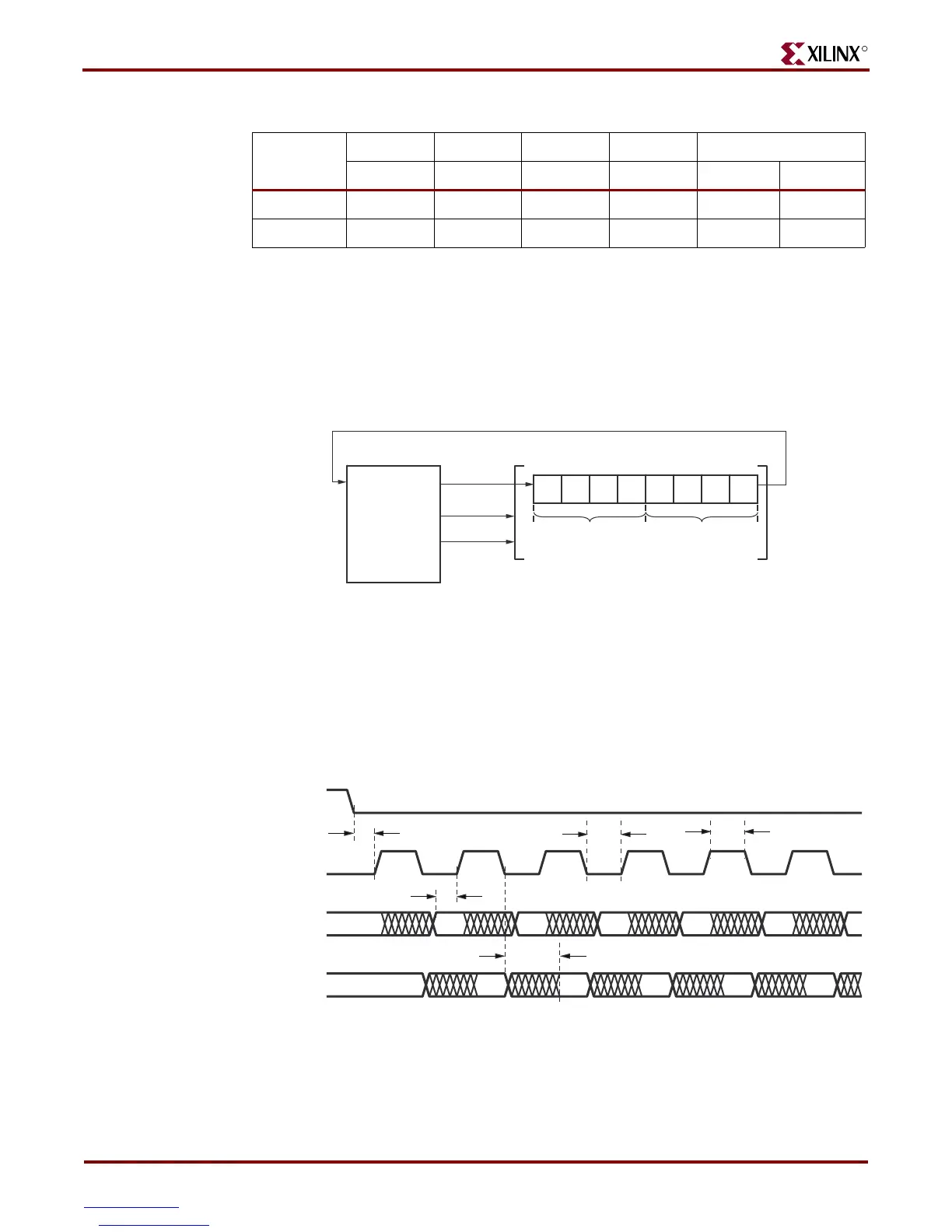
SPI Control Interface
Figure 10-3 highlights the SPI-based communications interface with the amplifier. The gain
for each amplifier is sent as an 8-bit command word, consisting of two 4-bit fields. The
most-significant bit, B3, is sent first.
The AMP_DOUT output from the amplifier echoes the previous gain settings. These
values can be ignored for most applications.
The SPI bus transaction starts when the FPGA asserts AMP_CS Low (see Figure 10-4). The
amplifier captures serial data on SPI_MOSI on the rising edge of the SPI_SCK clock signal.
The amplifier presents serial data on AMP_DOUT on the falling edge of SPI_SCK.
The amplifier interface is relatively slow, supporting only about a 10 MHz clock frequency.
-50 0 1 1 0 1.625 1.675
-100 0 1 1 1 1.6375 1.6625
Table 1 0 -2: Programmable Gain Settings for Pre-Amplifier (Continued)
Gain
A3 A2 A1 A0 Input Voltage Range
B3 B2 B1 B0 Minimum Maximum
Figure 10-3: SPI Serial Interface to Amplifier
Figure 10-4: SPI Timing When Communicating with Amplifier
7
Spartan-3E
FPGA
Master
0
A
1
A
2
A
3
A
0
B
1
B
2
B
3
B
0
A Gain B Gain
Slave: LTC2624-1
AMP_DOUT
SPI_MOSI
AMP_CS
SPI_SCK
UG257_10_03_060706
SPI_SCK
AMP_CS
SPI_MOSI
AMP_DOUT
76543 2
30
50
30
85 max
All timing is minimum in nanoseconds unless otherwise noted.
(from AMP)
(from FPGA)
Previous 7
UG570_10_04_060706
50