92 MicroBlaze Development Kit Spartan-3E 1600 Edition User Guide
www.xilinx.com UG257 (v1.1) December 5, 2007
Chapter 12: SPI Serial Flash
R
UCF Location Constraints
Figure 12-2 provides the UCF constraints for the SPI serial Flash PROM, including the I/O
pin assignment and the I/O standard used.
Configuring from SPI Flash
To configure the FPGA from SPI Flash, the FPGA mode select pins must be set
appropriately and the SPI Flash must contain a valid configuration image.
Setting the FPGA Mode Select Pins
Set the FPGA configuration mode pins for SPI mode, as shown in Figure 12-4. The location
of the configuration mode jumpers (J30) appears in Figure 12-3.
Figure 12-2: UCF Location Constraints for SPI Flash Connections
# some connections shared with SPI Flash, DAC, ADC, and AMP
NET "SPI_MISO" LOC = "N10" | IOSTANDARD = LVCMOS33 ;
NET "SPI_MOSI" LOC = "T4" | IOSTANDARD = LVCMOS33 | SLEW = SLOW | DRIVE = 6 ;
NET "SPI_SCK" LOC = "U16" | IOSTANDARD = LVCMOS33 | SLEW = SLOW | DRIVE = 6 ;
NET "SPI_SS_B" LOC = "U3" | IOSTANDARD = LVCMOS33 | SLEW = SLOW | DRIVE = 6 ;
NET "SPI_ALT_CS_JP11" LOC = "R12" | IOSTANDARD = LVCMOS33 | SLEW = SLOW | DRIVE = 6 ;
UG257_12_02_060806
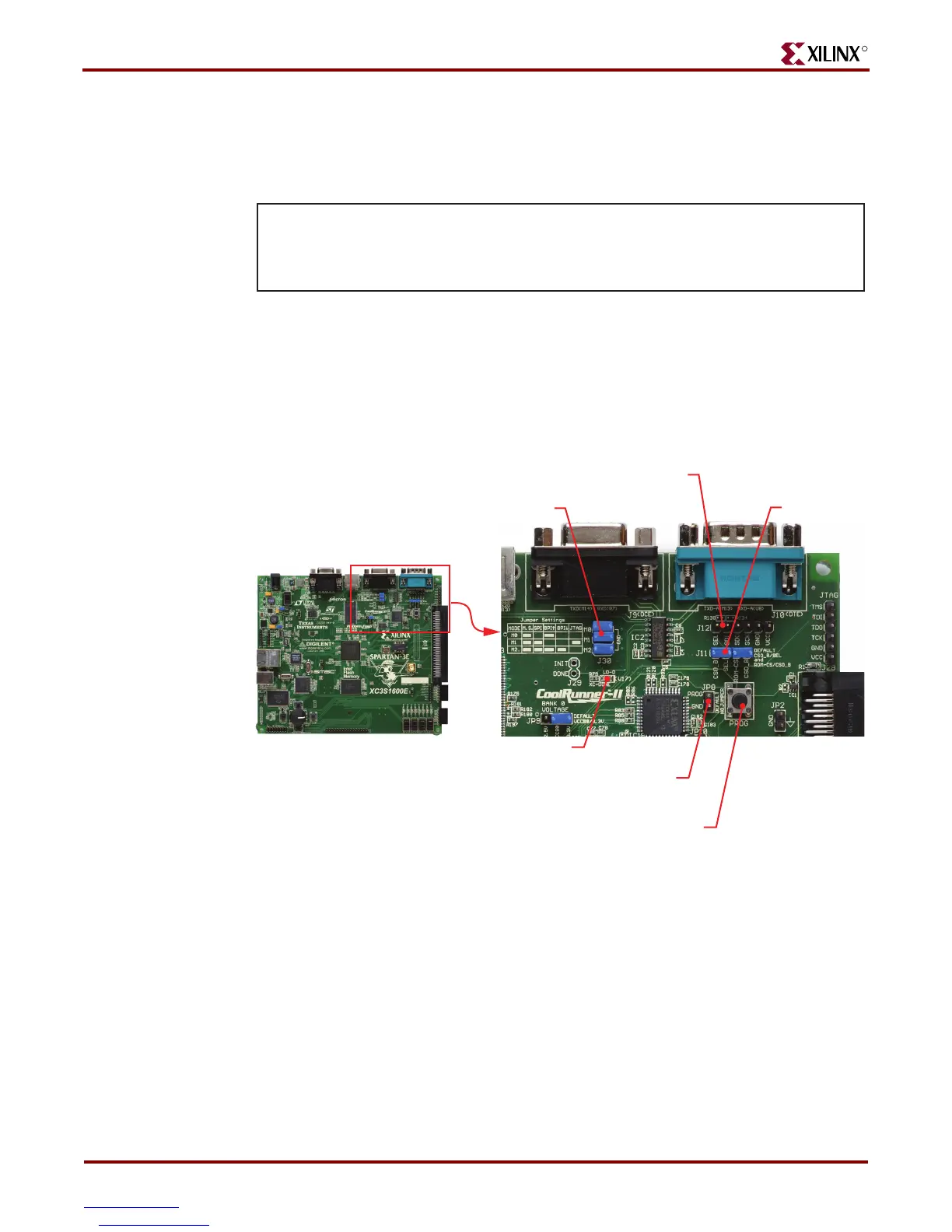
Figure 12-3: Configuration Options for SPI Mode
DONE Pin LED
(Lights up when FPGA successfully configured)
Spartan-3E
Development Board
Select SPI Mode using
the Jumper Settings table.
(Remove top jumper and
insert the bottom two)
Header J12
(XSPI Programming)
Jumper J11
UG257_12_03_061506
PROG_B Push Button Switch
(Press and release to
restart configuration.)
Jumper JP8 (XPSI)
(When programming SPI Flash using the XSPI
utility, insert jumper to hold PROG_B pin low.)