MicroBlaze Development Kit Spartan-3E 1600 Edition User Guide 53
UG257 (v1.1) December 5, 2007 www.xilinx.com
R
Chapter 6
VGA Display Port
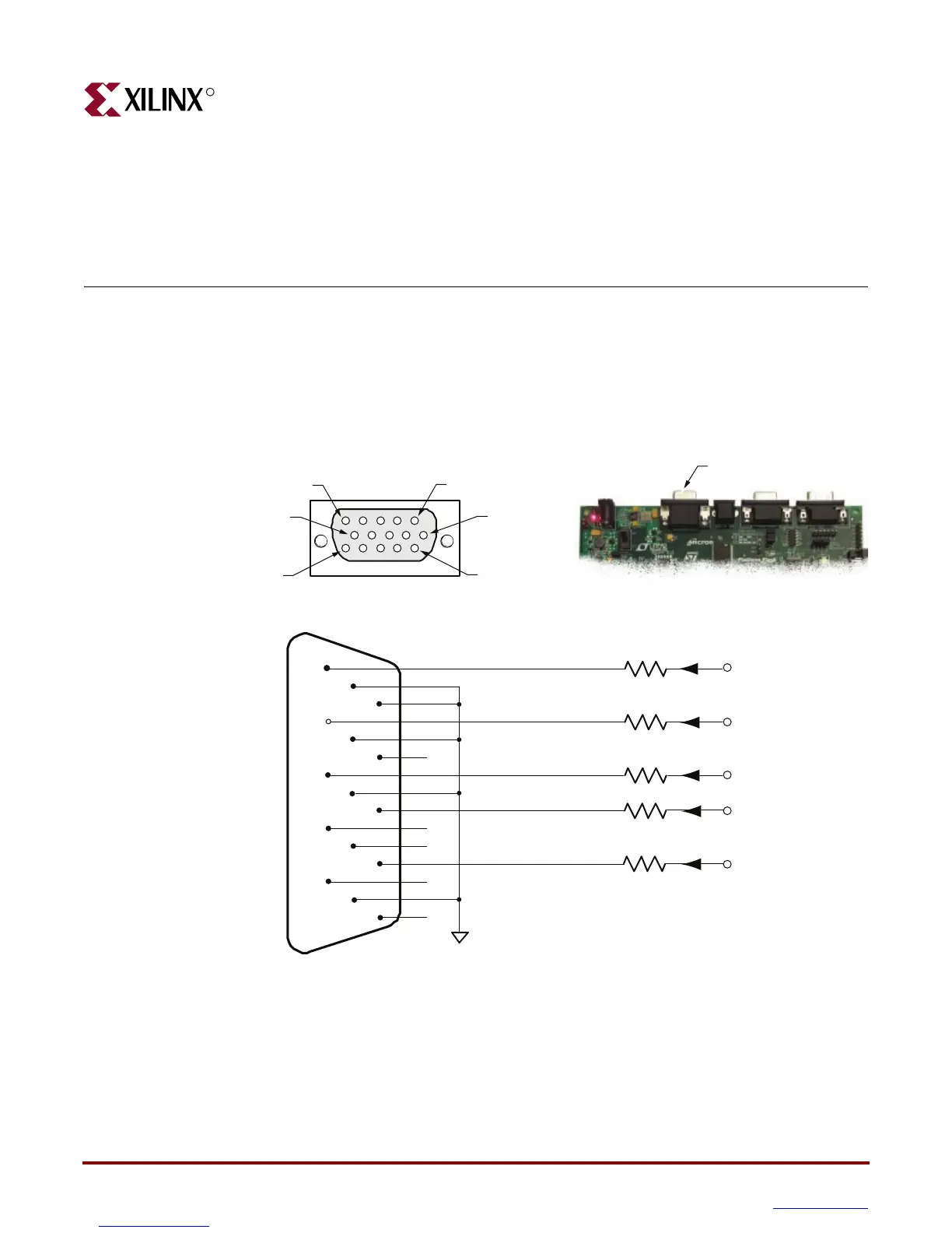
The MicroBlaze Development Kit board includes a VGA display port via a J15 connector.
Connect this port directly to most PC monitors or flat-panel LCDs using a standard
monitor cable. As shown in Figure 6-1, the VGA connector is the left-most connector along
the top of the board.
The Spartan-3E FPGA directly drives the five VGA signals via resistors. Each color line has
a series resistor, with one bit each for VGA_RED, VGA_GREEN, and VGA_BLUE. The
series resistor, in combination with the 75: termination built into the VGA cable, ensures
that the color signals remain in the VGA-specified 0V to 0.7V range. The VGA_HSYNC
and VGA_VSYNC signals using LVTTL or LVCMOS33 I/O standard drive levels. Drive
Figure 6-1: VGA Connections from Spartan-3E Starter Kit Board
DB15 VGA Connector
(front view)
1
6
11
2
7
12
3
8
13
4
9
14
5
10
15
GND
DB15
Connector
Red
Green
Blue
Horizontal Sync
Vertical Sync
270W
270W
270W
VGA_RED
VGA_GREEN
VGA_BLUE
VGA_HSYNC
VGA_VSYNC
(H14)
(H15)
(G15)
(F15)
(F14)
Pin 1
Pin 6
Pin 11
Pin 5
in 10
15
82.5W
82.5W
UG257_06_01_060506
DB15 VGA Connector