112 MicroBlaze Development Kit Spartan-3E 1600 Edition User Guide
www.xilinx.com UG257 (v1.1) December 5, 2007
Chapter 14: 10/100 Ethernet Physical Layer Interface
R
Ethernet PHY Connections
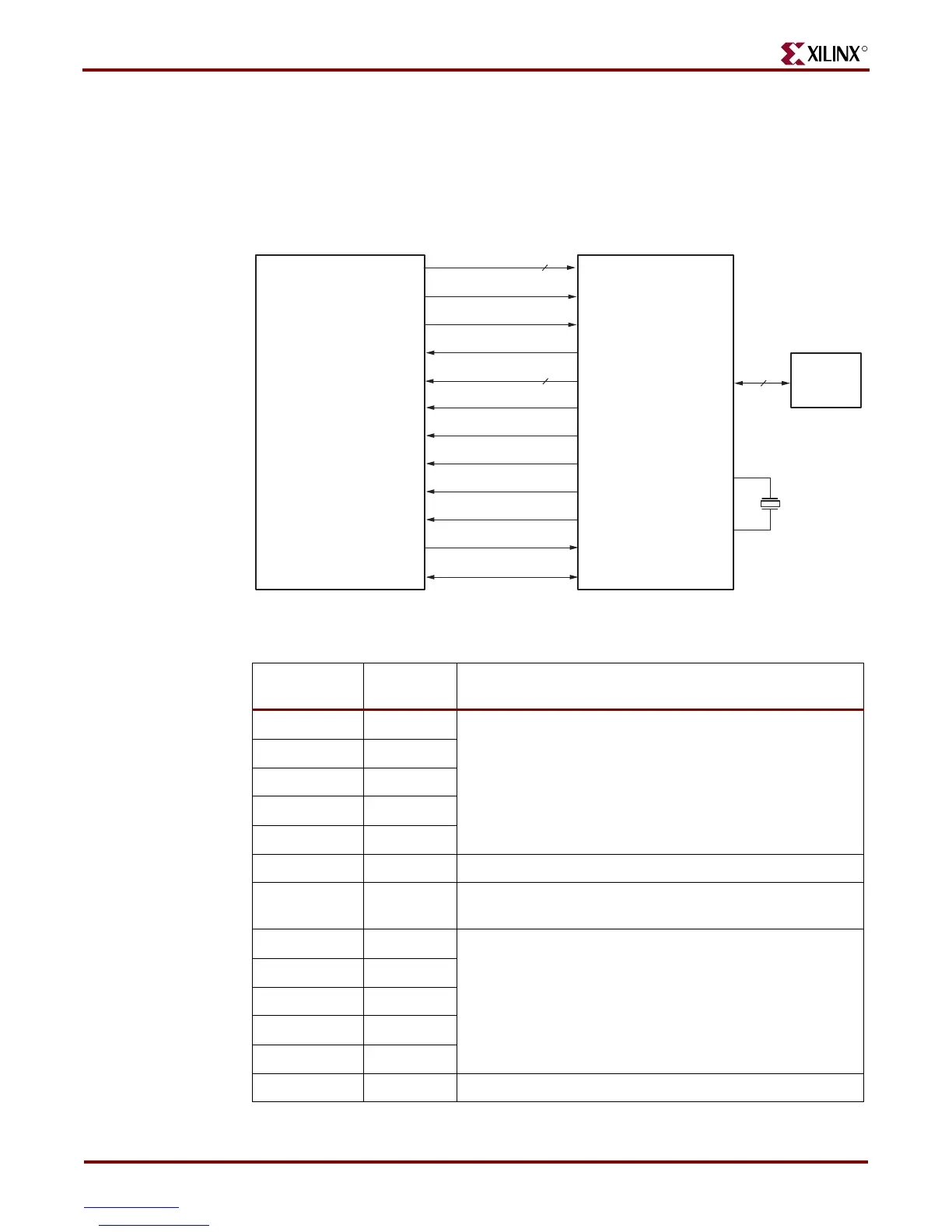
The FPGA connects to the LAN83C185 Ethernet PHY using a standard Media Independent
Interface (MII), as shown in Figure 14-2. A more detailed description of the interface
signals, including the FPGA pin number, appears in Table 14-1.
Figure 14-2: FPGA Connects to Ethernet PHY via MII
Table 1 4 -1: FPGA Connections to the LAN83C185 Ethernet PHY
Signal Name
FPGA Pin
Number Function
E_TXD<4> R6 Transmit Data to the PHY. E_TXD<4> is also the MII
Transmit Error.
E_TXD<3> T5
E_TXD<2> R5
E_TXD<1> T15
E_TXD<0> R11
E_TX_EN P15 Transmit Enable.
E_TX_CLK T7 Transmit Clock. 25 MHz in 100Base-TX mode, and 2.5 MHz
in 10Base-T mode.
E_RXD<4> U14 Receive Data from PHY.
E_RXD<3> V14
E_RXD<2> U11
E_RXD<1> T11
E_RXD<0> V8
E_RX_DV V2 Receive Data Valid.
See Table
E_TXD<3:0>
(T7)
Spartan-3E FPGA
E_TX_EN
E_TXD<4>
E_TX_CLK
TXD[3:0]
TXD4/TX_ER
TX_EN
TX_CLK
SMSC LAN83C185
10/100 Ethernet PHY
E_RXD<3:0>
E_RX_DV
E_MDIO
E_MDC
E_RX_CLK
E_RXD<4>
E_CRS
E_COL
RXD[3:0]
RX_DV
RXD4/RX_ER
RX_CLK
CRS
COL
MDC
MDIO
See Table
(V2)
(U14)
(V3)
(U13)
(U6)
(P9)
(U5)
(P15)
(R4)
RJ-45
Connector
25.000 MHz
UG257_14_02_060806