Home
Xilinx
Computer Hardware
MIcroBlaze Development Spartan-3E 1600E Kit
Page 145
Xilinx MIcroBlaze Development Spartan-3E 1600E Kit - Page 145
168 pages
Manual
Save Page as PDF
To Next Page
To Next Page
To Previous Page
To Previous Page
Loading...
MicroBlaze Development Kit Sparta
n-3E 1600 Edition User Guide
143
UG257 (v1.1) De
cember 5, 2007
www
.xilin
x.com
FPGA C
onfigurat
ions Set
tings, Pl
atform Flas
h PROM, SPI Serial Flash,
JT
A
G Connections
R
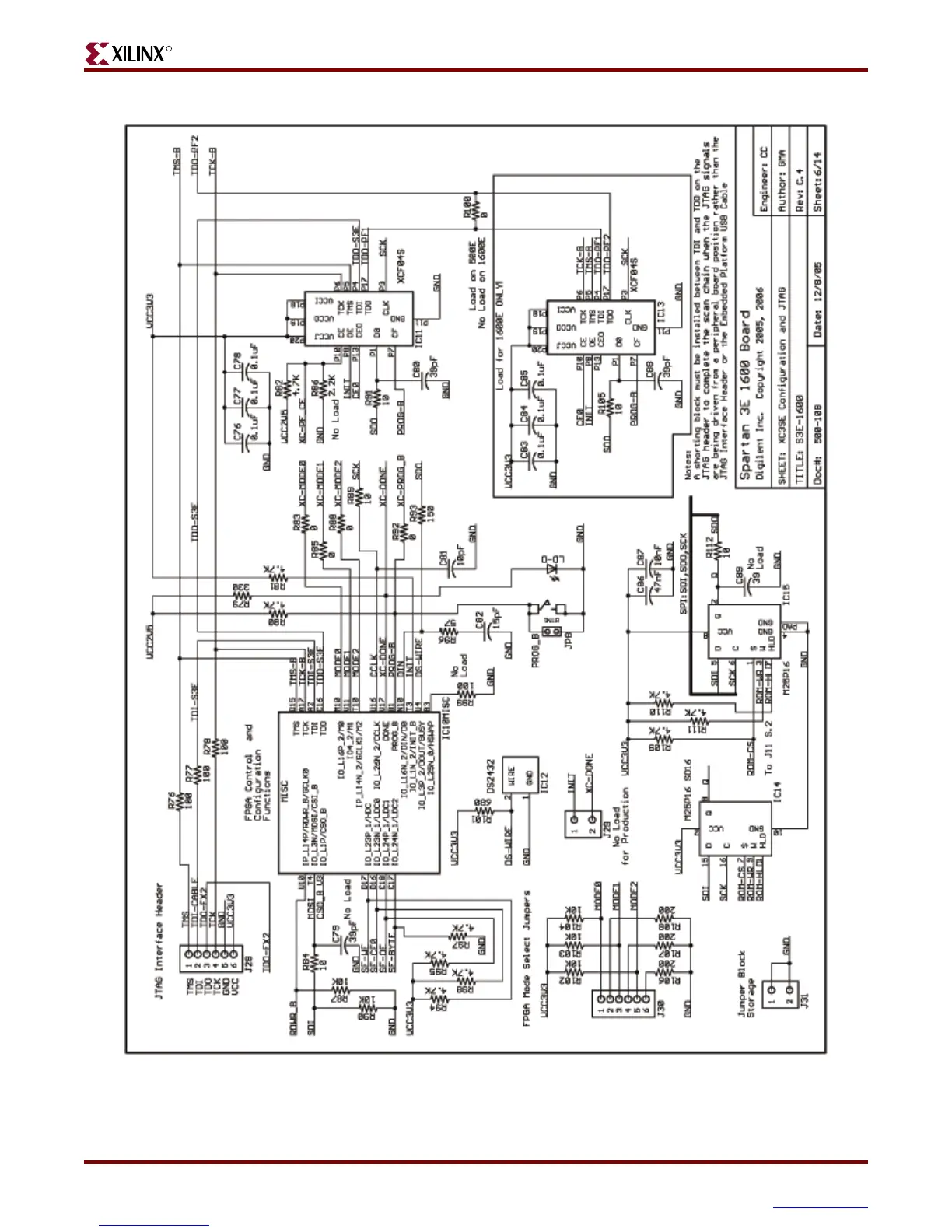
Figure 18-5:
Schematic Sheet 6
UG257_A05_060606
144
146
Table of Contents
Main Page
Table of Contents
3
Default Chapter
2
Revision History
2
Preface: about this Guide
9
Acknowledgements
9
Guide Contents
9
Additional Resources
10
Chapter 1: Introduction and Overview
11
Choose the Starter Kit Board for Your Needs
11
Advanced Spartan-3 Generation Development Boards
11
Learning Xilinx FPGA, CPLD, and ISE Development Software Basics
11
Spartan-3E FPGA Features and Embedded Processing Functions
11
Key Components and Features
12
Design Trade-Offs
13
Configuration Methods Galore
13
Voltages for All Applications
13
Related Resources
13
Chapter 2: Switches, Buttons, and Knob
15
Slide Switches
15
Locations and Labels
15
Operation
15
UCF Location Constraints
15
Push-Button Switches
16
Locations and Labels
16
Operation
16
UCF Location Constraints
17
Rotary Push-Button Switch
17
Locations and Labels
17
Operation
17
UCF Location Constraints
19
Discrete Leds
19
Locations and Labels
19
Operation
20
UCF Location Constraints
20
Related Resources
20
Chapter 3: Clock Sources
21
Overview
21
Clock Connections
22
Voltage Control
22
50 Mhz On-Board Oscillator
22
Auxiliary Clock Oscillator Socket
22
SMA Clock Input or Output Connector
22
UCF Constraints
22
Clock Period Constraints
23
Location
23
Related Resources
23
Chapter 4: FPGA Configuration Options
25
Configuration Mode Jumpers
27
PROG Push Button
28
DONE Pin LED
28
Programming the FPGA, CPLD, or Platform Flash PROM Via USB
29
Connecting the USB Cable
29
Programming Via Impact
30
Programming Platform Flash PROM Via USB
32
Chapter 5 : Character LCD Screen
43
Overview
43
Character LCD Interface Signals
44
Voltage Compatibility
44
Interaction with Intel Strataflash
45
UCF Location Constraints
45
LCD Controller
46
Memory Map
46
Command Set
48
Operation
52
Four-Bit Data Interface
52
Initializing the Display
53
Transferring 8-Bit Data over the 4-Bit Interface
53
Disabling the Unused LCD
54
Writing Data to the Display
54
Related Resources
54
Chapter 6: VGA Display Port
55
Signal Timing for a 60 Hz, 640X480 VGA Display
56
VGA Signal Timing
58
UCF Location Constraints
59
Related Resources
59
Chapter 7 : RS-232 Serial Ports
61
Overview
61
UCF Location Constraints
63
Chapter 8: PS/2 Mouse/Keyboard Port
65
Keyboard
66
Mouse
68
Voltage Supply
69
UCF Location Constraints
69
Related Resources
69
Chapter 9: Digital to Analog Converter (DAC)
71
SPI Communication
71
Disable Other Devices on the SPI Bus to Avoid Contention
72
Interface Signals
72
Communication Protocol
73
SPI Communication Details
73
Specifying the DAC Output Voltage
74
DAC Outputs a and B
74
DAC Outputs C and D
75
UCF Location Constraints
75
Related Resources
75
Chapter 10: Analog Capture Circuit
77
Digital Outputs from Analog Inputs
78
Programmable Pre-Amplifier
79
Interface
79
Programmable Gain
79
SPI Control Interface
80
UCF Location Constraints
81
Analog to Digital Converter (ADC)
81
Interface
81
SPI Control Interface
81
UCF Location Constraints
82
Disable Other Devices on the SPI Bus to Avoid Contention
83
Connecting Analog Inputs
83
Related Resources
83
Chapter 11: Intel Strataflash Parallel nor Flash PROM
85
Strataflash Connections
86
Shared Connections
89
Character LCD
89
SPI Data Line
89
Xilinx XC2C64A CPLD
89
UCF Location Constraints
90
Address
90
Data
90
Control
91
Setting the FPGA Mode Select Pins
91
Related Resources
91
Chapter 12: SPI Serial Flash
94
UCF Location Constraints
94
Configuring from SPI Flash
94
Setting the FPGA Mode Select Pins
94
Creating an SPI Serial Flash PROM File
95
Downloading the Design to SPI Flash
100
Downloading the SPI Flash Using XSPI
100
Additional Design Details
103
Shared SPI Bus with Peripherals
103
Jumper Block J11
104
Multi-Package Layout
104
Other SPI Flash Control Signals
104
Programming Header J12
104
Variant Select Pins, VS[2:0]
104
Related Resources
106
Chapter 13: DDR SDRAM
107
DDR SDRAM Connections
108
UCF Location Constraints
110
Address
110
Data
110
Control
111
Reserve FPGA VREF Pins
111
Related Resources
111
Chapter 14: 10/100 Ethernet Physical Layer Interface
114
Ethernet PHY Connections
114
Microblaze Ethernet IP Cores
115
UCF Location Constraints
116
Related Resources
116
Chapter 15: Expansion Connectors
117
Hirose 100-Pin FX2 Edge Connector (J3)
117
Connector Pinout and FPGA Connections
118
Voltage Supplies to the Connector
118
Compatible Board
120
Differential I/O
120
Mating Receptacle Connectors
120
UCF Location Constraints
124
Six-Pin Accessory Headers
125
Header J1
125
Header J2
125
Header J4
126
UCF Location Constraints
126
Connectorless Debugging Port Landing Pads (J6)
127
Related Resources
128
Chapter 16: XC2C64A Coolrunner-II CPLD
129
UCF Location Constraints
130
Cpld
131
FPGA Connections to CPLD
131
Related Resources
132
Related Resources
133
UCF Location Constraints
133
Appendix A Schematics
135
Default Chapter
136
FX2 Expansion Header, 6-Pin Headers, and Connectorless Probe Header
136
RS-232 Ports, VGA Port, and PS/2 Port
138
Ethernet PHY, Magnetics, and RJ-11 Connector
140
Voltage Regulators
142
Appendix A: Schematics
144
Chapter 17 : DS2432 1-Wire SHA-1 EEPROM
144
Connections
144
FPGA Configurations Settings, Platform Flash PROM, SPI Serial Flash, JTAG
144
FPGA I/O Banks 0 and 1, Oscillators
146
FPGA I/O Banks 2 and 3" "Power Supply Decoupling
148
XC2C64A Coolrunner-II CPLD
152
Linear Technology ADC and DAC
154
Intel Strataflash Parallel nor Flash Memory and Micron DDR SDRAM
156
Buttons, Switches, Rotary Encoder, and Character LCD
158
DDR SDRAM Series Termination and FX2 Connector Differential Termination
160
Related product manuals
Xilinx MicroBlaze
18 pages
Xilinx Alveo U250
26 pages
Xilinx 7 Series
306 pages
Xilinx Alveo U50
31 pages
Xilinx FMC XM107
8 pages
Xilinx SelectIO 7 Series
188 pages
Xilinx Alveo U200
53 pages
Xilinx virtex-5 fpga
385 pages
Xilinx ChipScope Pro
226 pages
Spartan-3E FPGA Sample Pack
2 pages