104 www.xilinx.com RocketIO™ Transceiver User Guide
UG024 (v3.0) February 22, 2007
Chapter 3: Analog Design Considerations
R
Pre-emphasis Techniques
In pre-emphasis, the initial differential voltage swing is boosted to create a stronger rising
or falling waveform. This method compensates for high frequency loss in the transmission
media that would otherwise limit the magnitude of this waveform. The effects of
pre-emphasis are shown in four scope screen captures, Figure 3-2 through Figure 3-5 on
the pages following.
The STRONG notation in Figure 3-3 is used to show that the waveform is greater in voltage
magnitude, at this point, than the LOGIC or normal level (i.e., no pre-emphasis).
A second characteristic of RocketIO transceiver pre-emphasis is that the STRONG level is
reduced after some time to the LOGIC level, thereby minimizing the voltage swing
necessary to switch the differential pair into the opposite state.
Lossy transmission lines cause the dissipation of electrical energy. This pre-emphasis
technique extends the distance that signals can be driven down lossy line media and
increases the signal-to-noise ratio at the receiver.
It should be noted that high pre-emphasis settings are not appropriate for short links (a
fraction of the maximum length of 40 inches of FR4). Excessive pre-emphasis can actually
degrade the bit error rate (BER) of a multi-gigabit link. Careful simulation and/or lab
testing of the system should always be used to verify that the optimal pre-emphasis setting
is in use. Consult the Virtex-II Pro RocketIO™ Multi-Gigabit Transceiver Characterization
Summary for more detailed information on the waveforms to be expected at the various
pre-emphasis levels.
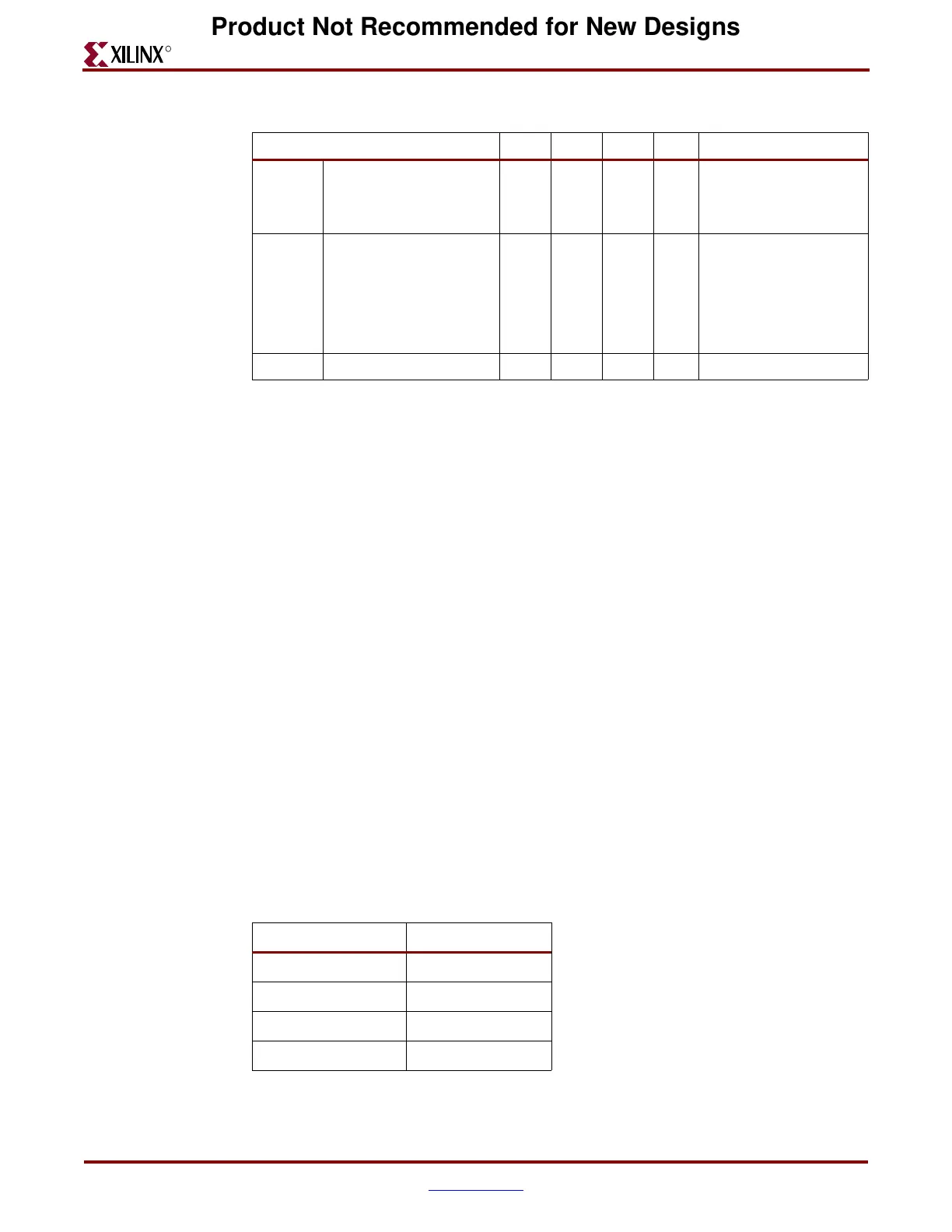
The four levels of pre-emphasis are shown in Table 3-2.
V
TCM
Common mode output
voltage range (no
transmission line
connected)
1.1 1.5 V
V
TCM
Common mode output
voltage range
(transmission line
connected)
1.1 2.0 V The common mode
depends on coupling (DC
or AC), VTTX, VTRX, and
differential swing. Spice
simulation gives the exact
common mode voltage for
any given system.
V
ISKEW
Differential output skew 15 ps
Table 3-1: Differential Transmitter Parameters (Continued)
Parameter Min Typ Max Units Conditions
Table 3-2: Pre-emphasis Values
Attribute Values Emphasis (%)
010
120
225
333
Product Not Recommended for New Designs