RocketIO™ Transceiver User Guide www.xilinx.com 79
UG024 (v3.0) February 22, 2007
Channel Bonding (Channel Alignment)
R
Channel Bonding (Channel Alignment)
Overview
Some gigabit I/O standards such as XAUI specify the use of multiple transceivers in
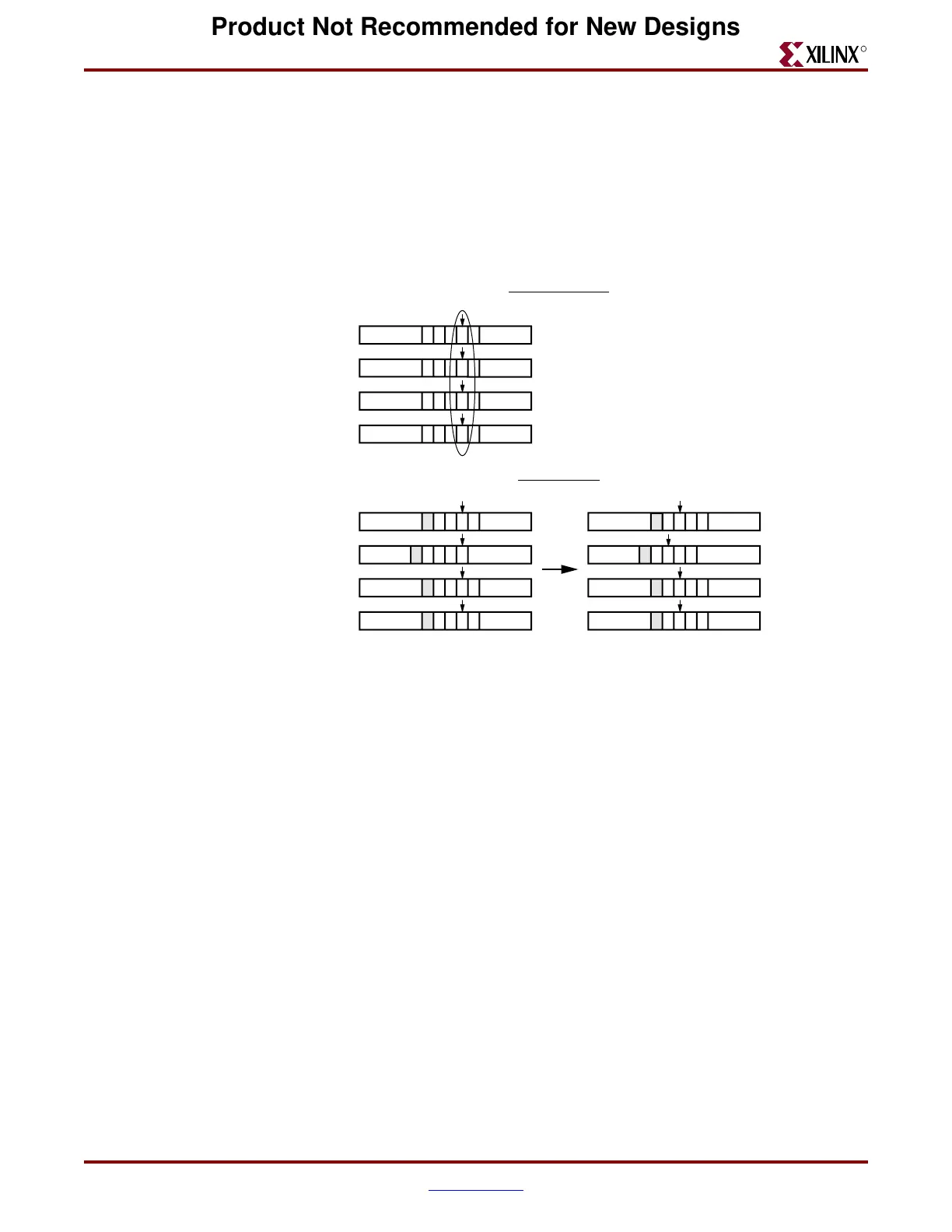
parallel for even higher data rates. Words of data are split into bytes, with each byte sent
over a separate channel (transceiver). See Figure 2-22.
The top half of the figure shows the transmission of words split across four transceivers
(channels or lanes). PPPP, QQQQ, RRRR, SSSS, and TTTT represent words sent over the
four channels.
The bottom-left portion of the figure shows the initial situation in the FPGA’s receivers at
the other end of the four channels. Due to variations in transmission delay—especially if
the channels are routed through repeaters—the FPGA core might not correctly assemble
the bytes into complete words. The bottom-left illustration shows the incorrect assembly of
data words PQPP, QRQQ, RSRR, etc.
To support correction of this misalignment, the data stream includes special byte
sequences that define corresponding points in the several channels. In the bottom half of
Figure 2-22, the shaded “P” bytes represent these special characters. Each receiver
recognizes the “P” channel bonding character, and remembers its location in the buffer. At
some point, one transceiver designated as the Master instructs all the transceivers to align
to the channel bonding character “P” (or to some location relative to the channel bonding
character). After this operation, the words transmitted to the FPGA core are properly
aligned: RRRR, SSSS, TTTT, etc., as shown in the bottom-right portion of Figure 2-22. To
ensure that the channels remain properly aligned following the channel bonding
operation, the Master transceiver must also control the clock correction operations
described in the previous section for all channel-bonded transceivers.
Figure 2-22: Channel Bonding (Alignment)
PQRS T
PQRS T
PQRS T
PQRS T
PQRS T
PQRS T
PQRS T
PQRS T
PQRS T
PQRS T
PQRS T
PQRS T
Before channel bonding After channel bonding
Read
RXUSRCLK
Read
RXUSRCLK
Full word SSSS sent over four channels, one byte per channel
Channel (lane) 0
Channel (lane) 1
Channel (lane) 2
Channel (lane) 3
DS083-2_16_010202
In Transmitters:
In Receivers:
Product Not Recommended for New Designs