Virtex-5 FPGA ML561 User Guide www.xilinx.com 129
UG199 (v1.2.1) June 15, 2009
Hardware Schematic Diagram
R
After the SHL bit is configured, these settings normally are not changed.
• Select the LCD bias settings.
♦ The duty cycle is selected as 1/65 by hardwiring the controller IC pads on the
display PCB.
♦ The LCD bias is set to:
- 1/7: when the BIAS bit is 0
- 1/9: when the BIAS bit is 1
The following steps are performed next:
• Start the onboard converter, regulator, and follower
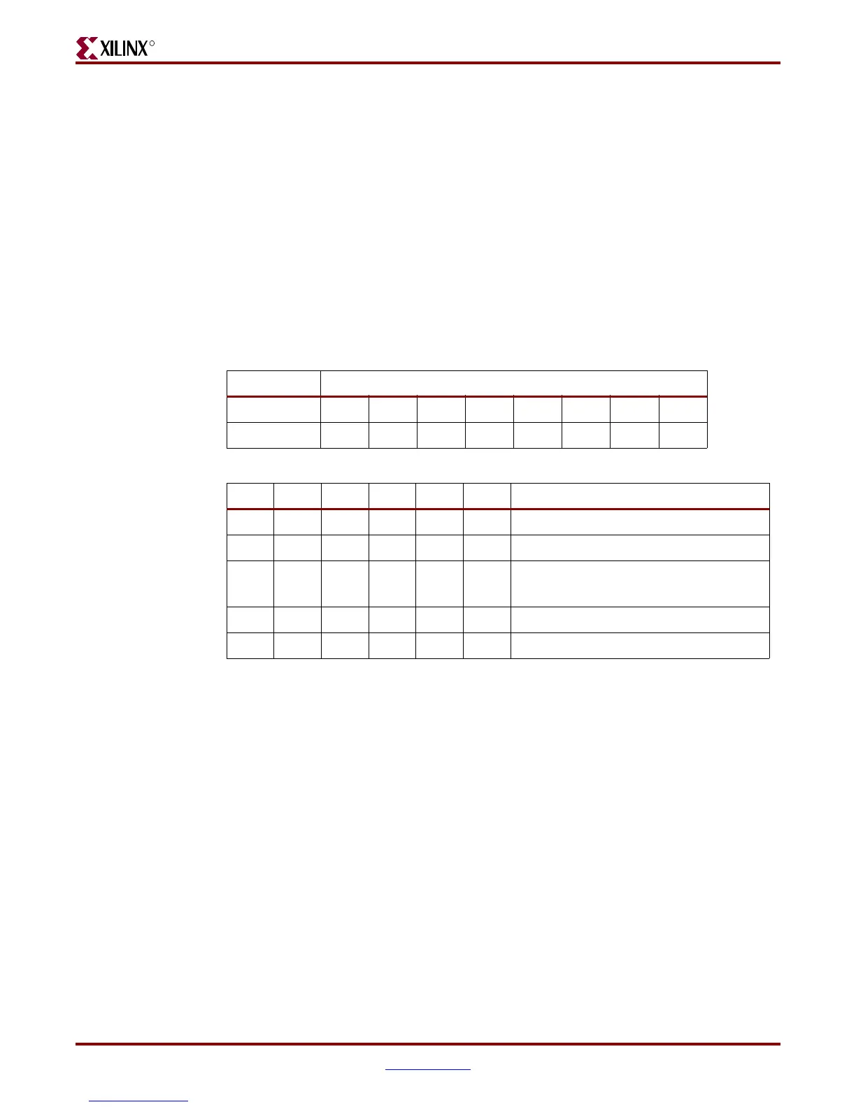
• Set the regulator resistor values (see Table C-4)
• Configure the reference voltage register parameters (see Table C-5)
At startup of the LCD controller (after RESETB operation), the resistor and reference
voltage values are:
• Resistor selection is: 0,0,0
• Reference voltage is: 1,0,0,0,0,0
The resistor selection value MUST be set to 101b when using this LCD panel.
After the display is brought to operational mode, it is best to wait at least 1 ms to ensure the
stabilization of power supply levels. After this time, all other necessary display
initializations can be performed.
Tab l e C -4 : Resistor Value Settings
3-Bit Data Settings (R2 R1 R0)
000 001 010 011 100 101 110 111
1+(Rb/Ra) 1.90 2.19 2.55 3.02 3.61 4.35 5.29 6.48
Tab l e C -5 : Reference Voltage Parameters
SV5 SV4 SV3 SV2 SV1 SV0 Reference Voltage Parameter (α)
000000 0
000001 1
..
..
..
..
…
..
..
..
..
..
..
..
..
..
111110 62
111111 63
 Loading...


