ZC706 Evaluation Board User Guide www.xilinx.com 73
UG954 (v1.5) September 10, 2015
Feature Descriptions
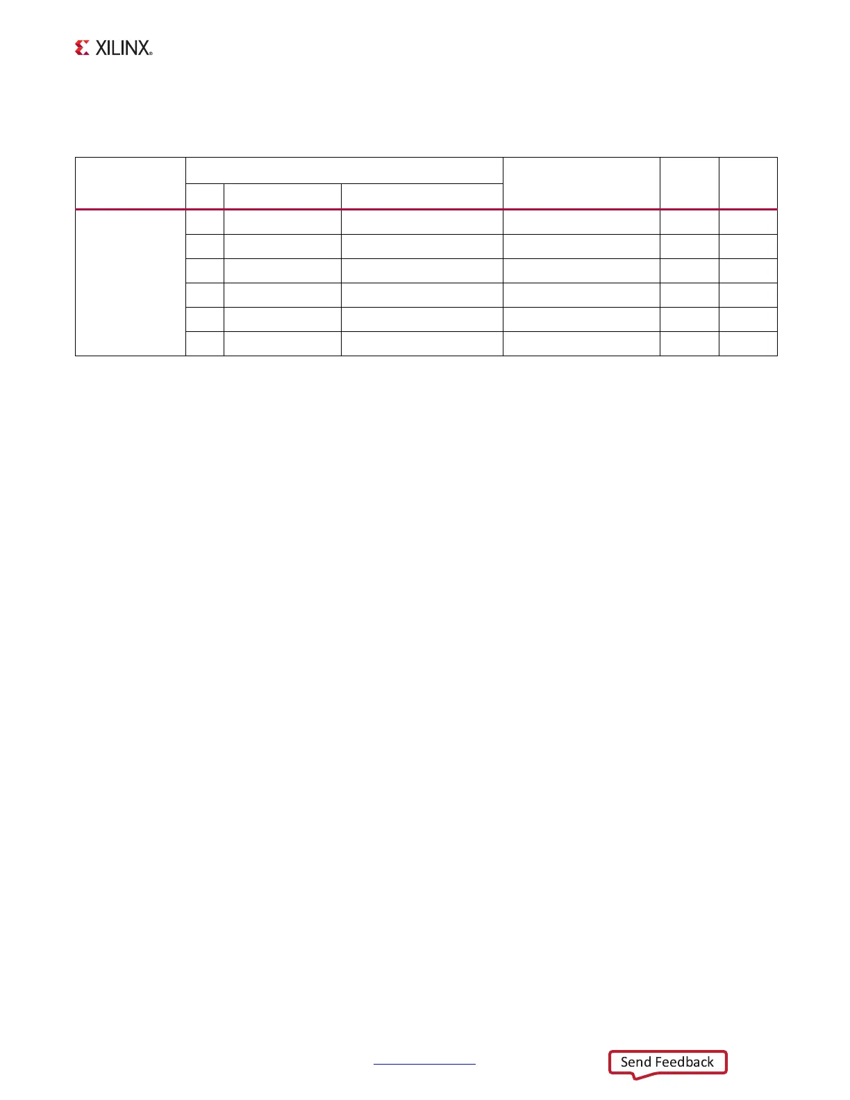
Table 1-34 shows the ZC706 board TI power system configuration for controller U48.
Table 1-34: ZC706 TI Controller U48 Power System Configuration
Sequencer
Schematic Page
Regulator Type, U# Voltage Current
Page Contents Net Name
U48 PMBus
Addr 101
5 Rails
49 UCD90120A
50 Addr 101, Rail 1 VCCINT LMZ31520 U42
(1)
1.0V 16A
51 Addr 101, Rail 2 VCCAUX, VCC1V8 LMZ31710 U98
(2)
1.8V 10A
52 Addr 101, Rail 3 VCC1V5_PL LMZ31506 U85
(3)
1.5V 6A
53 Addr 101, Rail 4 VADJ_FPGA,VADJ LMZ31506 U86
(2)
2.5V 6A
54 Addr 101, Rail 5 VCC3V3_FPGA,VCC3V3 LMZ31710 U15
(4)
3.3V 10A
Notes:
ZC706 boards prior to Rev. 2.0 implemented different voltage regulators for VCCINT, VCCAUX/VCC1V8, VCC1V5_PL,
VADJ_FPGA/VADJ and VCC3V3_FPGA/VCC3V3. Refer to UG954 v1.3 and earlier, and to the schematic for the particular version
of the ZC706 board prior to Rev. 2.0. Notes on ZC706 boards prior to Rev. 2.0:
1. VCCINT is implemented utilizing 2xLMZ22008 8A components (U42, U43) in parallel which provides 16A capability.
2. The 1.8V rails are supplied from a LMZ22010 10A component (U98).
3. VCC1V5_PL and the 2.5V rails are supplied from TPS84621 6A components (U85, U86).
4. The 3.3V rails are supplied from a LMZ22010 10A component (U15).