ZCU102 Evaluation Board User Guide www.xilinx.com 15
UG1182 (v1.2) March 20, 2017
Chapter 2: Board Setup and Configuration
Default Switch and Jumper Settings
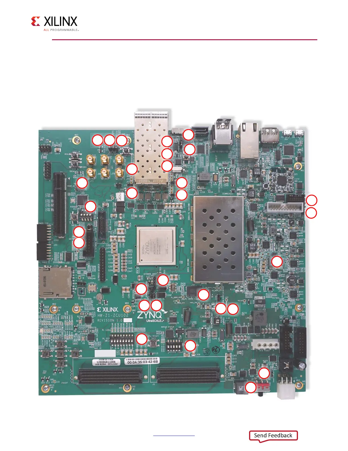
Figure 2-2 shows the board jumper header and DIP switch locations. Each numbered
component shown in the figure is keyed to Table 2-2 (for default switch settings) or
Table 2-3 (for default jumper settings). Both tables reference the respective schematic page
numbers.
X-Ref Target - Figure 2-2
Figure 2-2: DIP Switch and Board Header Jumper Locations
;