ZCU111 Board User Guide 61
UG1271 (v1.1) August 6, 2018 www.xilinx.com
Chapter 3: Board Component Descriptions
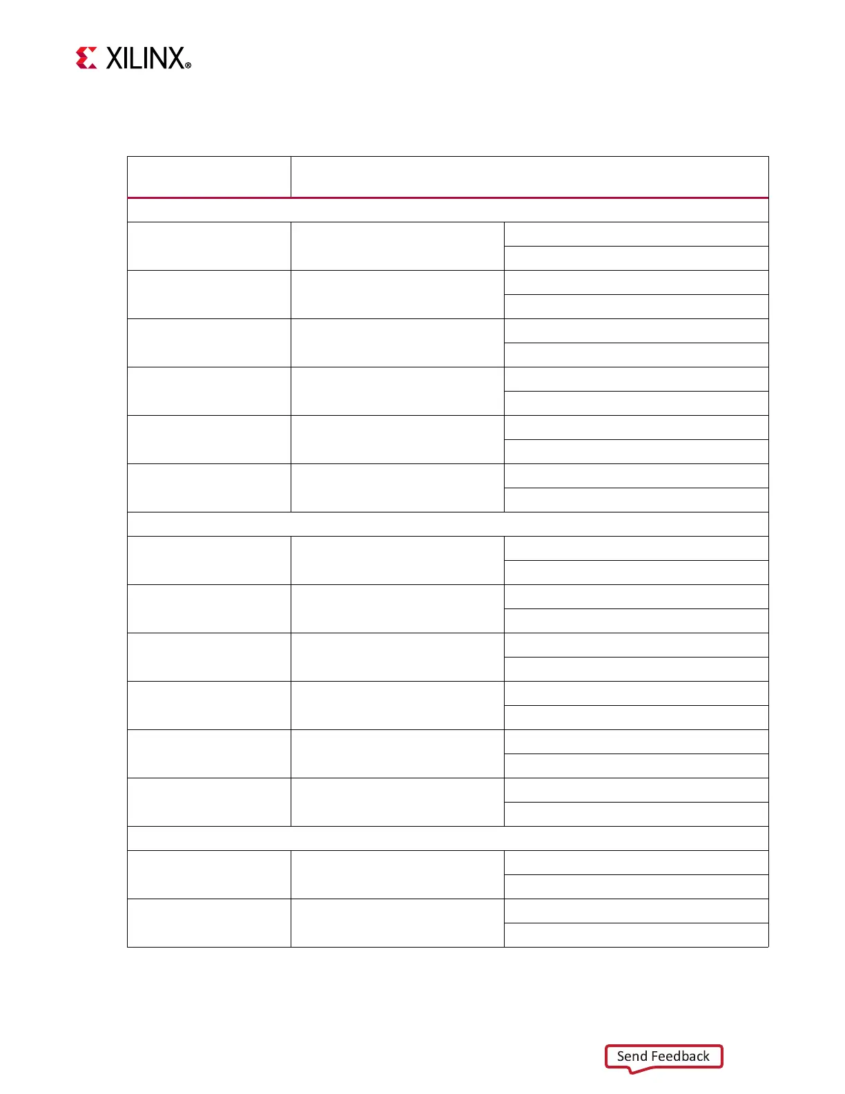
Tab l e 3- 2 1 lists the SFP28 module connections to RFSoC U1.
Table 3-21: SFP28 Control and Status Board Test Points
SFP28 Control/
Status Signal
Board Connection
SFP0 J27
(1)(2)
SFP_TX_FAULT Test point J28
High = Fault
Low = Normal operation
SFP_TX_DISABLE Jumper J29
Off = SFP disabled
On = SFP enabled
SFP_MOD_DETECT Test point J30
High = Module not present
Low = Module present
SFP_RS0 PU R276/PD R278
PU R276 = Full RX bandwidth
PD R278 = Reduced RX bandwidth
SFP_RS1 PU R277/PD R279
PU R277 = Full TX bandwidth
PD R279 = Reduced TX bandwidth
SFP_LOS Test point J31
High = Loss of receiver signal
Low = Normal operation
SFP1 J32
(1)(2)
SFP_TX_FAULT Test point J33
High = Fault
Low = Normal operation
SFP_TX_DISABLE Jumper J35
Off = SFP disabled
On = SFP enabled
SFP_MOD_DETECT Test point J34
High = Module not present
Low = Module present
SFP_RS0 PU R281/PD R283
PU R281 = Full RX bandwidth
PD R283 = Reduced RX bandwidth
SFP_RS1 PU R282/PD R284
PU R282 = Full TX bandwidth
PD R284 = Reduced TX bandwidth
SFP_LOS Test point J36
High = Loss of receiver signal
Low = Normal operation
SFP2 J37
(1)(2)
SFP_TX_FAULT Test point J38
High = Fault
Low = Normal operation
SFP_TX_DISABLE Jumper J40
Off = SFP disabled
On = SFP enabled