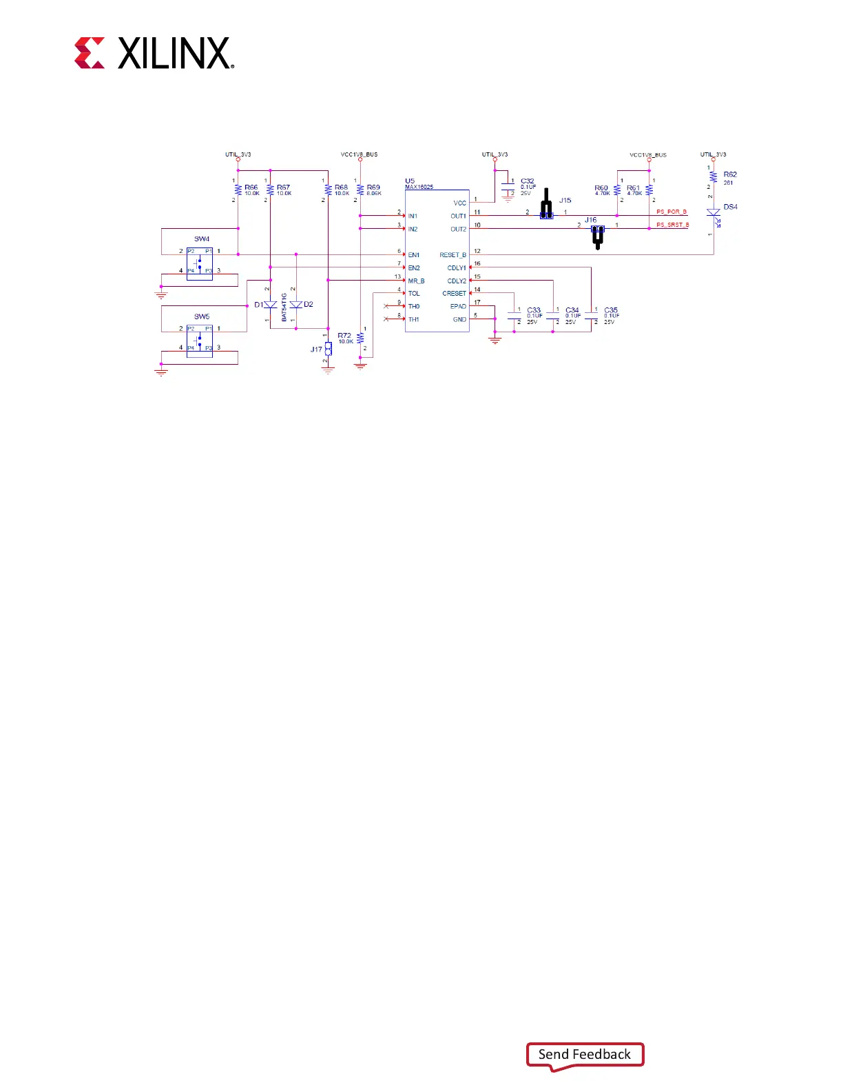
Figure 21: POR_B SW4 and PS SRST_B SW5 Pushbutton Switches
PS_POR_B Reset
Depressing and then releasing pushbuon SW4 causes net PS_POR_B to strobe Low. This reset
is used to hold the PS in reset unl all PS power supplies are at the required voltage levels. It
must be held Low through PS power-up. PS_POR_B must be generated by the power supply
power-good signal. When the voltage at IN1 is below its threshold or EN1 (P.B. switch SW4 is
pressed) goes Low, OUT1 (PS_POR_B) goes Low.
PS_SRST_B Reset
Depressing and then releasing pushbuon SW5 causes net PS_SRST_B to strobe Low. This reset
is used to force a system reset. It can be ed or pulled High, and can be High during the PS
supply power ramps. When the voltage at IN2 is below its threshold or EN2 (P.B. switch SW5 is
pressed) goes Low, OUT2 (PS_SRST_B) goes Low.
Acve-Low Reset Output RESET_B asserts when any of the monitored voltages (IN_) falls below
its respecve threshold, any EN_ goes Low, or MR is asserted. RST_B remains asserted for the
reset me-out period aer all of the monitored voltages exceed their respecve threshold, all
EN_ are High, all OUT_ are high, and MR is de-asserted. See the Zynq UltraScale+ Device Technical
Reference Manual (UG1085) for more informaon about resets.
Board Power System
[Figure 2, callout 39, 40, and 41]
The ZCU208 evaluaon board uses power management ICs (PMIC) and regulators from Inneon
Integrated Circuits and MPS to supply the core and auxiliary voltages listed in the following table.
Reference schemac 038-05003-01.
Chapter 3: Board Component Descriptions
UG1410 (v1.0) July 8, 2020 www.xilinx.com
ZCU208 Board User Guide 61

 Loading...


