EasyManuals Logo

Xinje DS5B Series User Manual

Xinje DS5B Series
109 pages
To Next Page IconTo Next Page
To Previous Page IconTo Previous Page
Page #37 background imageLoading...
Page #37 background image
When upper device is 5V differential output, please use this wiring diagram.
Please note: P+24V and D+24V must be vacant.
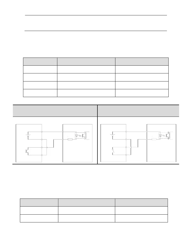
SI input signal
Please use relay or open collector transistor to connect. When using relay, please choose
micro-current relay. Otherwise, the contact will be not good.
Signal input
Function
Support model
SI1
S-ON/enable
5B
SI2
ALM-RS/alarm reset
5B
SI3
P-OT/forward run prohibition
5B
SI4
N-OT/reverse run prohibition
5B
Open collector (24V power supply)
Relay (24V power supply)
Upper device servo drive
SI
+24V
+
COM2
Y2
0V
+24V
R=2.2KΩ
Upper device servo drive
R=2.2KΩ
+24V
0V
Y2
COM2
+
+24V
SI
Note: the max allowable voltage and current of open collector output circuit:
Voltage: max DC30V
Current: max DC50mA
SO output terminal
Signal output
Function
Support model
SO1
COIN/positioning complete
5B
SO2
ALM/alarm
5B

Table of Contents

Questions and Answers:

Question and Answer IconNeed help?

Do you have a question about the Xinje DS5B Series and is the answer not in the manual?

Xinje DS5B Series Specifications

General IconGeneral
BrandXinje
ModelDS5B Series
CategoryServo Drives
LanguageEnglish

Related product manuals