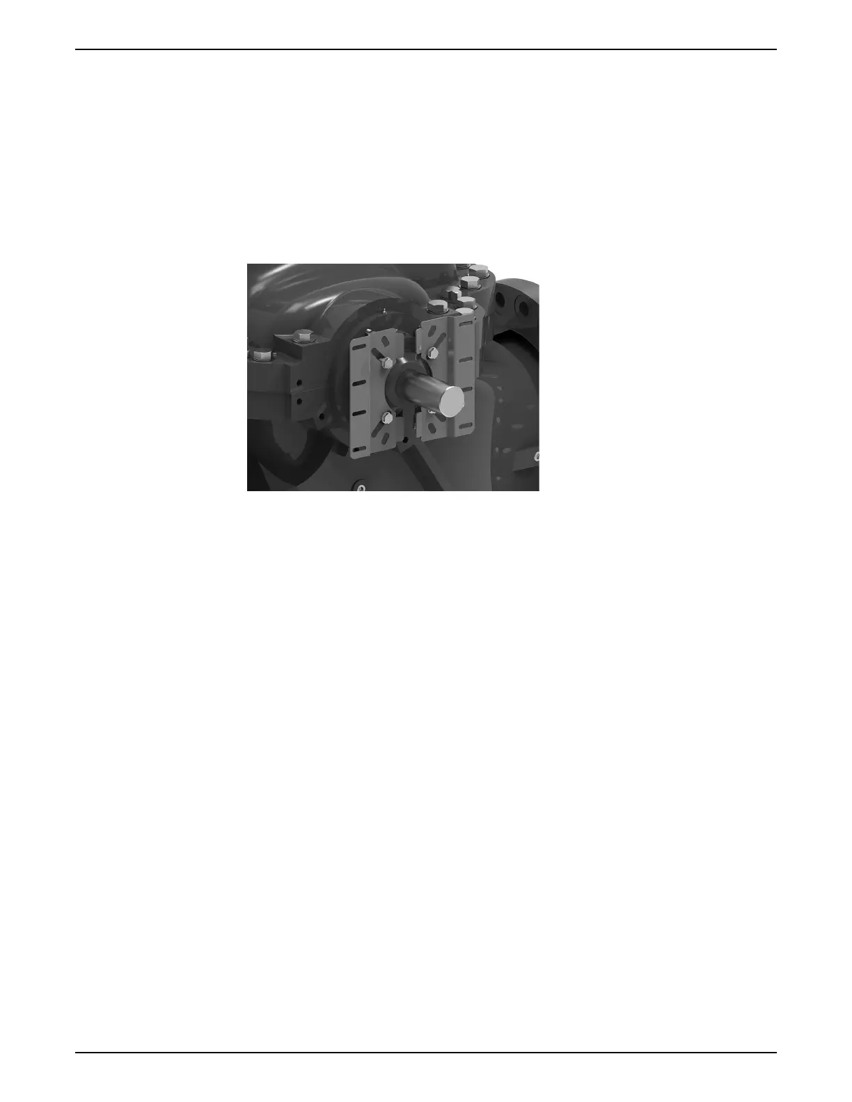
1. If the two mounting brackets [5] are not already mounted on the inboard bearing
gland (see Figure 39: Large bracket mounted to pump bearing gland (without guard
assembly) on page 97), attach them as follows:
a) Place one washer [9] onto each of four bearing gland bolts [8].
b) Feed one bolt [8] through each of the angled slots on the mounting bracket [5]
such that the shaft of the bolt protrudes away from the rounded tabs (as in Figure
36: Fully assembled coupling guard — small bracket on page 95 and Figure 37: Fully
assembled coupling guard — large bracket on page 96).
c) Place one threadless spacer [10] on each of the bolts [8].
d) Mount each bracket/fastener set to the inboard bearing gland, adjusting the bolts
[8] in the slots to the correct gland size as needed.
Figure 39: Large bracket mounted to pump bearing gland (without guard assembly)
2. Couple the lower halves of the outer [2] and inner [1] guard assemblies by fastening
the two hex head bolts [6] into the bottom faces of the hex guard assembly.
Be sure to thread each of the hex head bolts through a self-retaining washer [7] placed
behind along the inside of the bottom outer guard [2].
3. Position the coupled assembly beneath the coupler. Attach the bottom half of the
inner guard [1] to the mounting bracket [5].
a) Align the horizontal slots of the mounting bracket [5] with the holes located on the
front of the inner guard [1].
b) Thread two hex bolts [6] through the mounting bracket [5] and into the weld nuts
located behind the holes of the inner guard [1].
Be sure to place a self-retaining washer [7] between the mounting bracket [5] and
inner guard [1] while threading each hex bolt into the inner guard.
4. Place the top half of the inner guard [1] onto the floating lower guard assembly and
attach the top half of the inner guard [1] to the mounting bracket [5] by following steps
3a and 3b.
5. Secure the outer guard assembly as follows:
a) Slightly thread two hex head bolts [6] into self-retaining washers [7] that should be
placed along the inside of the outer guard [2]. Ensure the bolts are placed in the
middle viewing slots located on top of the outer guard [2].
b) Place the outer guard [2] over the inner guard assembly [1] and align the two outer
guard [2] halves with one another.
c) Place a square spacer [4] between the flanges of the outer guard assembly [1]. For
best results, ensure the spacer piece [4] is aligned with the front of the outer guard
assembly [2] near the motor.
d) Slide a fastener clip [3] over each spacer [4] location and thread a hex head bolt [6]
through both the clip and spacer to secure both parts to the outer guard assembly.
6 Maintenance
e-XC INSTRUCTION MANUAL 97