By using an analogue sensor, two adjustable alarm limits can be used, one for warning (“B”-
alarm) and one for pump stop (“A”-alarm).
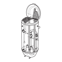
3.6.4 Pump memory
The pump memory is located inside the junction box of the pump. The memory is loaded
with data from the factory, which is then uploaded to the MAS system at first start-up.
The data that is uploaded contains the following features:
•
Data plate information
• Sensor types and alarm settings recommended by the manufacturer
• Operational data and data to support service:
– Histograms of temperatures, vibrations, and cycle length
– Start and stop registration
– Service log with a maximum of 200 lines of text
– Conditions to prompt for service based on for example, running time, number of starts
and stops or specific dates
For more information, see the MAS 711 Installation and User Manual.
3.7 Monitoring with MiniCAS II
This table shows the parameters which can be tracked with the MiniCAS II monitoring
system.
Parameter Sensor Standard or optional
Stator winding temperature One of the following choices:
• Standard: 3 thermal switches
• Optional: 3 PTC thermistors
Standard
Leakage in the inspection
chamber
Float switch leakage sensor (FLS) Standard
Leakage in the junction box Float switch leakage sensor (FLS) Optional
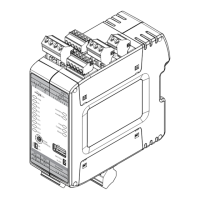
3.7.1 MiniCAS II
One MiniCAS II is required for each pump.
1. Combined power and signal cable
2. MiniCAS II
MiniCAS II features include the following:
• Two pump sensors
• Signal leads are incorporated in the SUBCAB
®
power cable.
• LED alarm indication
3.8 Column adapters
There are two accessories which can be used to install these pumps in slightly larger
columns:
• Diffuser adapter
• Flange adapter
3 Product Description
20 P7030, P7035, P7040 Installation, Operation, and Maintenance Manual
 Loading...