1. Disconnect the sensor wires.
2.
Measure the resistance to check the status of the sensor and wiring according to the
values in
Sensors
on page 18.
3. Measure between each sensor lead to ground (earth) to establish that the resistance is
infinite (or at least several Megaohm).
6.4 Check the leakage sensors
If the pump is connected to the MAS monitoring system, then it is recommended that the
sensors be checked in the MAS unit. Otherwise, use a multimeter.
1. Check the float switch (FLS) in the inspection chamber, according to the values in
Sensors
on page 18.
Measure ohms by using a multimeter to establish either of the conditions below (or both if
the sensor is accessible).
2. Check the float switch (FLS) in the junction box (connection housing).
6.4.1 FLS
Table 18: Float switch sensor (FLS)
Description Measured value Fault values
The float switches are leakage
sensors.
The float switches are located in
the lower part of the stator
housing and in the junction box.
Resistance. 2 sensor variants:
FLS:
• Normal: 1530 ohm
• Alarm: 330 ohm
FLS 10:
• Normal: 1200 ohm
• Alarm: 430 ohm
> 10% (approx.) deviation
from rated ohm values
indicates sensor fault, or fault
in the wiring.
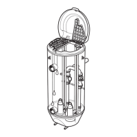
6.5 Changing the oil
This figure shows where the plugs for change of oil are placed on the unit.
1. Oil plug
2.
Inspection plug
3. Oil plug
4. Outer screw
Figure 35: With a cooling jacket
6 Maintenance
64 P7030, P7035, P7040 Installation, Operation, and Maintenance Manual
 Loading...