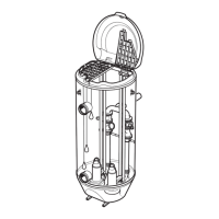
Item Description Connection
D Junction box leakage 12–lead sensor cable
E Stator winding 1, Pt100 12–lead sensor cable
F Vibration, VIS10 12–lead sensor cable
G Support bearing, Pt100 12–lead sensor cable
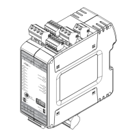
H Pump memory Power cable sensor leads
Table 11: Pump memory
Power Cable Lead Number Description
T1 Supply 12V +
T2 Supply, ground
T3 RS485A
T4 RS485B
Table 12: Vibration, VIS10
12–lead SUBCAB Number Color
9 Brown, +
10 Blue, –
2. Connect the mains leads (L1, L2, L3, and ground (earth) ) to the starter equipment.
For information about the phase sequence and the color codes of the leads, see
Cable
charts
on page 48.
3. Check the functionality of the monitoring equipment:
a) Check that the signals and the tripping function work properly.
b) Check that the relays, lamps, fuses, and connections are intact.
Replace any defective equipment.
4.6.8 Power cable phase sequence
In the following figure, the triangle marked “L1,” “L2” and “L3” shows the phase sequence.
L2
L1 L2 L3
L3L1
WS000578E
1
2
3
4
T2T1
7
6
5
8
Figure 15: Correct phase sequence
Item Description
1 L1 cable lead Brown
2 L2 cable lead Black
3 L3 cable lead Gray
4 Earth PE or ground lead cable
5 T1 cable lead (control element) In cables with both power conductors and
4 Installation
P7030, P7035, P7040 Installation, Operation, and Maintenance Manual 47
 Loading...