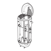
Item Description
6 control element.
MAS 801: See the SIO manual for T1, T2,
and drain wire connections.
T2 cable lead (control element)
7 Screen (drain wire)
8 Power cable to unit
4.6.9 Cable bending radius, weight and diameter
Table 13: SUBCAB
®
Cable Minimum bending
radius in mm
Weight in kg/m Outer diameter,
minimum-maximum in
mm
4G4 + 2x1.5 200 0.63 Ø 20.0–22.0
4G6 + 2x1.5 240 0.83 Ø 24–26
4G10 + S(2x0.5) 240 0.85 Ø 24–26
4G16 + S(2x0.5) 260 1.13 Ø 26–28
4G25 + S(2x0.5) 320 1.70 Ø 32–34
4G35 + S(2x0.5) 350 2.24 Ø 35–37
3x50 + 2G35/2 + S(2x0.5) 350 2.6 Ø 35–37
3x70 + 2G35/2 + S(2x0.5) 380 3.3 Ø 38–41
Table 14: SUBCAB
®
screened cables
Cable Minimum bending
radius in mm
Weight in kg/m Outer diameter,
minimum-maximum in
mm
S3x6 + 3x6/3 + S(4x0.5) 200 0.55 Ø 20–22
S3x10 + 3x10/3 + S(4x0.5) 240 0.95 Ø 24–26
S3x16 + 3x16/3 + S(4x0.5) 240 1.1 Ø 24–26
S3x25 + 3x16/3 + S(4x0.5) 290 1.4 Ø 29–31
S3x35 + 3x16/3 + S(4x0.5) 320 2.0 Ø 32–34
S3x50 + 3x25/3 + S(4x0.5) 380 3.0 Ø 38–40
S3x70 + 3x35/3 +2 S(2x0.5) 420 3.5 Ø 42–44
4.7 Cable charts
Connection locations
The figures in this section illustrate how to interpret the connection strip symbols.
4 Installation
48 P7030, P7035, P7040 Installation, Operation, and Maintenance Manual
 Loading...