10.Connect the SUBCAB cable phase leads to the starter equipment according to the
diagram in
Power cable phase sequence
on page 47.
11.Perform the system setup by using the Setup wizard and other commissioning
procedures in the chapter “System Setup” in the SIO Manual for the MAS 801.
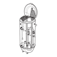
4.6.6.1 Terminals used in Ex applications
For Ex applications, the stator winding temperature sensors are not connected to terminals
51 and 63 on the PEM. They are connected to the T3 and T4 terminals on the separate
plinth.
• Thermal contacts must be wired separately to break contactor circuit directly.
• Thermistors must be wired to a Safety Integrity Level (SIL)-approved thermistor relay.
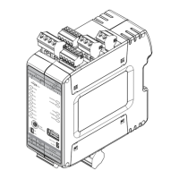
T3, T4
WS008219C
51
63
81
80
24
23
22
21
20
19
4
3
38
37
11
12
13
14
1
2
9
10
34
33
17
18
16
15
Terminal Description Terminal Description
37, 38 Temperature support bearing,
Pt100
1, 2 Leakage: Inspection chamber or
stator housing, FLS/FLS10
3, 4 Temperature main bearing, Pt100 9, 10 Leakage junction box, FLS/
FLS10
19, 20 Temperature stator winding 1,
Pt100
34, 33 Leakage, inspection chamber:
FLS10
21, 22 Temperature stator winding 2,
Pt100
15 T1 power supply and
communication
23, 24 Temperature stator winding 3,
Pt100
16 T2 power supply and
communication
80, 81 Pump current, CT 17 Not used
11, 12 V
out
+12 VDC, GND 18 Not used
4 Installation
44 P7030, P7035, P7040 Installation, Operation, and Maintenance Manual
 Loading...