• The cables must be in good condition, not have any sharp bends, and not be
pinched.
• The sheathing must not be damaged and must not have indentations or be
embossed at the cable entry.
• The minimum bending radius must not be below the accepted value.
• The cables must have the appropriate temperature rating.
4.3 Connect the wiring harness to the control panel
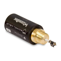
1. Connect the female circular connector of the wiring harness to the FST
module.
2. Connect the spliced terminals of the wiring harness to the control panel.
Wire color
Control panel
PrimeGuard 2
terminal
PV102P terminal Description
Orange Key switch Batt Key switch Batt V+
Black 15 6, 7, and 8 BATT-
Brown 12 14 DIG IN 1
Green 19 10 CAN LO
Yellow 20 11 CAN HI
Red 14 18 BATT +
White 4 12 RS 485 L
Blue 3 13 RS 485 H
4 Electrical Installation
14 FST Installation, Operation, and Maintenance Manual