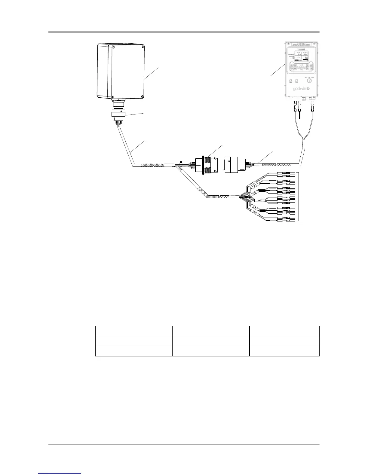
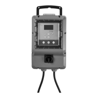
1. FST module
2. I/O extension cable for the FST module
3. Wiring harness for the FST module
4. Control panel
5. Spliced terminals that connect to relays, analog signal devices, or digital signal
devices
6. HDP26 connector
7. HDP24 connector
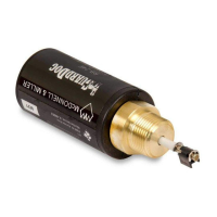
4.5 Connect a flowmeter to the control panel
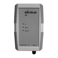
1. Connect the signal isolator to the control panel.
2. Set the DIP switch 7 to the ON position.
3. Connect the signal isolator to a flowmeter.
Wire color Flowmeter Signal isolator
Red wire Analog output + I+
Black wire Analog output - GND
4 Electrical Installation
16 FST Installation, Operation, and Maintenance Manual