7. Close the control panel and tighten the two screws again.
8. Set the parameters for the fuel level transducer on the control panel.
See Set the parameters for the fuel level transducer on page 26.
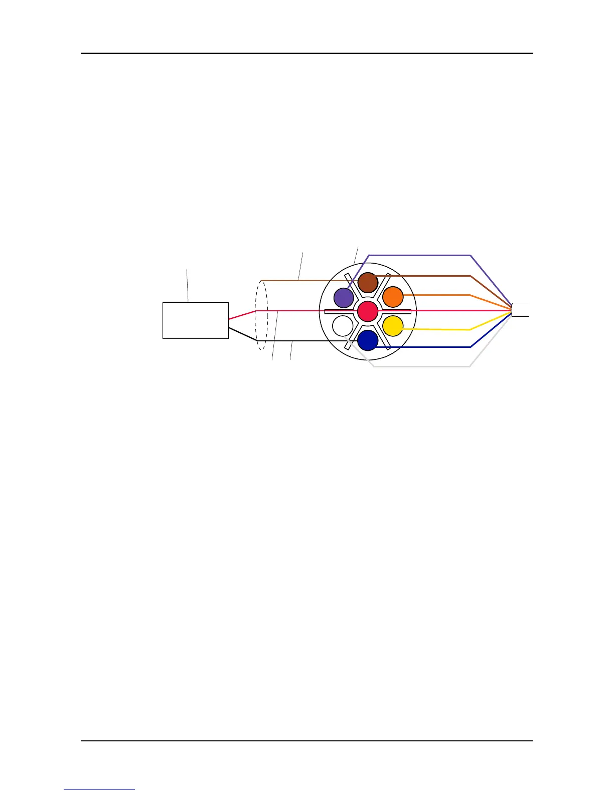
4.9 Connect the sump level transducer
1. Connect the sump level transducer to the 7-pin connector of the pigtail
harness.
2. Connect the other connector of the pigtail harness to the 7-pin connector of
the control panel.
1. Sump level transducer
2. 7-pin connector of the pigtail harness
3. Red wire
4. Black wire
5. Shield
3. Set the parameters for the sump level transducer on the control panel.
See Set the parameters for the sump level transducer on page 27.
4.10 Connect devices to IO extension cable
Connect 4-20 mA field sensors
1. Connect a passive 4-20 mA field sensor to the AI1 spliced terminals of the
I/O extension cable.
This sensor is not externally powered. It requires power from FST.
2. Connect an active 4-20 mA field sensor to the AI2 spliced terminals of the
I/O extension cable.
This sensor is externally powered. It does not require power from FST.
4 Electrical Installation
22 FST Installation, Operation, and Maintenance Manual