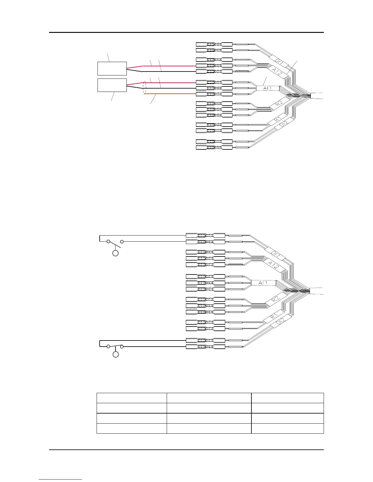
1. Passive 4-20 mA sensor
2. Active 4-20 mA sensor
3. AI1 spliced terminals of the I/O extension cable
4. AI2 spliced terminals of the I/O extension cable
5. Red wire
6. Black wire
7. Shield
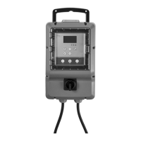
Connect the float switches
Connect a float switch to the DI1 or DI2 spliced terminals of the I/O
extension cable.
Connect relays
As applicable, connect 120VAC, 5A device R1 and R2 spliced terminals of
the I/O extension cable.
R1 COM and NO R2 COM and NO R2 COM and NC
5 A @ 30 VDC 5 A @ 30 VDC 5 A @ 30 VDC
xA @ 120 VAC xA @ 120 VAC xA @ 120 VAC
yA @ 240 VAC yA @ 240 VAC yA @ 240 VAC
4 Electrical Installation
FST Installation, Operation, and Maintenance Manual 23