Page 51FT-2000D OPERATING MANUAL
IPO
(
INTERCEPT POINT OPTIMIZATION
)
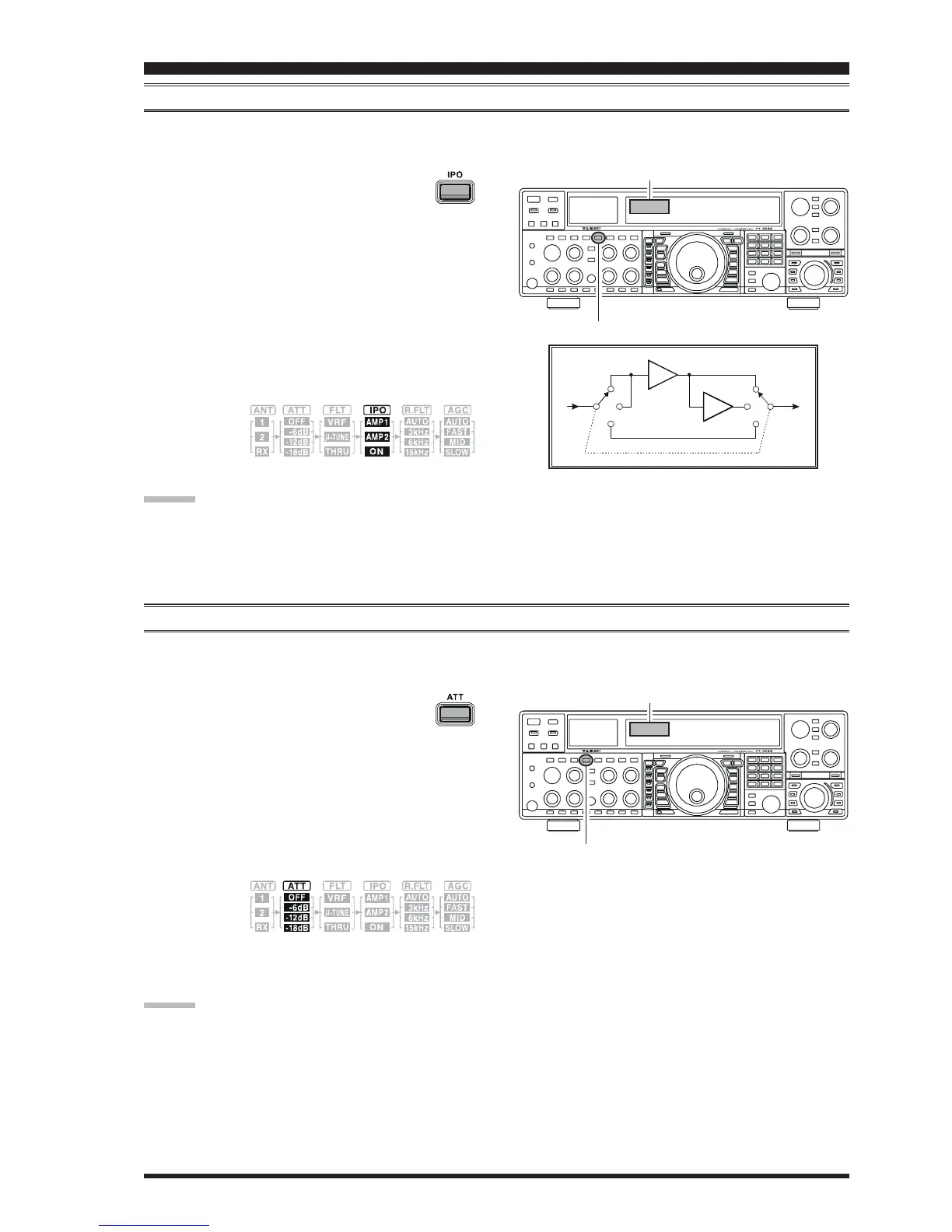
The IPO feature allows the operator to optimize the characteristics of the receiver front end, depending on the current noise
level and the strength of incoming signals.
Press the
[
IPO
]
button several times to set the
desired characteristic of the receiver front end,
per the chart below.
AMP1AMP1
AMP1AMP1
AMP1: Amplifies the incoming signal path using a
low distortion RF preamplifier (gain: approx.
10 dB).
AMP2AMP2
AMP2AMP2
AMP2: Amplifies incoming signal path using a 2-
stage low-distortion RF preamplifier (total
gain: approx. 17 dB).
ONON
ONON
ON: Bypasses the RF preamplifier, yielding di-
rect feed to the first mixer.
The selected receiver RF preamplifier will be indicated in
the IPO column
of the Receiver
Configuration
Indicator on the display.
ADVICE:
On the 10 MHz and lower bands, it generally is not necessary to use any preamplifier at all; selecting the “
ONON
ONON
ON” position
described above will increase the strong-signal-handling capability of the receiver, and generally will result in more pleas-
ant reception due to reduced noise. If you can hear band noise with the preamplifiers disengaged, then a preamplifier is
generally not needed.
ATT
Even with the IPO function on, extremely strong local signals or high noise can still degrade reception. In such situations,
you can use the
[
ATT
]
button to insert 6, 12, or 18-dB of RF attenuation in front of the RF amplifier.
Receiver Configuration Indicator
[
IPO
]
Button
1. Press the
[
ATT
]
button several times to set
the desired attenuation level, per the chart
below.
OFFOFF
OFFOFF
OFF: Attenuator is Off
–
6 dB6 dB
6 dB6 dB
6 dB: The incoming signal power is reduced by 6
dB (Signal voltage reduced by 1/2)
–
12 dB12 dB
12 dB12 dB
12 dB: The incoming signal power is reduced by 12
dB (Signal voltage reduced by 1/4)
–
18 dB18 dB
18 dB18 dB
18 dB: The incoming signal power is reduced by 18
dB (Signal voltage reduced by 1/8)
The selected
attenuation
level will be
indicated in the ATT column of the Receiver Configu-
ration Indicator on the display.
Receiver Configuration Indicator
[
ATT
]
Button
CONVENIENCE FEATURES
ADVICE
::
::
:
The Attenuator affects both the Main (VFO-A) and Sub (VFO-B) bands.
If background noise causes the S-meter to deflect on clear frequencies, press the
[
ATT
]
button until the S-meter drops to
about “S-1.” This setting optimizes the trade-offs between sensitivity, noise, and interference immunity. Also, once you have
tuned in a station you want to work, you may want to reduce sensitivity further (or add more attenuation) by pressing the
[
ATT
]
button to a more setting. This reduces the strength of all signals (and noise) and can make reception more comfort-
able, important especially during long QSOs. When looking for weak signals on a quiet band, you will want maximum
sensitivity, so the IPO should be disabled and the
[
ATT
]
button should be set to “
OFFOFF
OFFOFF
OFF.” This situation is typical during quiet
times on frequencies above 21 MHz, and when using a small or negative-gain receiving antenna on other bands.
2. To restore full signal strength through the Attenuator
circuit area, press the
[
ATT
]
button to restore the ATT
display to the “
OFFOFF
OFFOFF
OFF” position.
AMP1
AMP
AMP
AMP2
ON