Page 52 FT-2000D OPERATING MANUAL
RF GAIN
(
SSB/CW/AM MODES
)
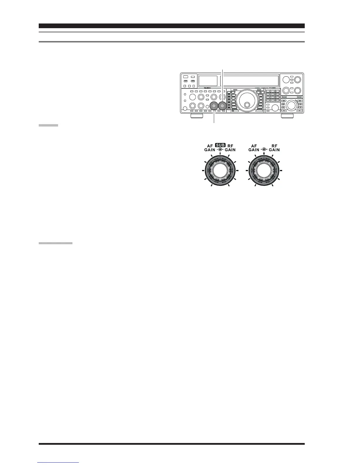
The RF Gain controls provide manual adjustment of the gain levels for the receiver RF and IF stages, to account for noise
and/or signal strength conditions at the moment.
1. The Main
[
RF GAIN
]
knob should, initially, be ro-
tated to the fully clockwise position. This is the point
of maximum sensitivity, and counter-clockwise rota-
tion will gradually reduce the system gain.
2. The Sub
[
RF GAIN
]
knob operates identically to the
Main
[
RF GAIN
]
knob. The fully clockwise position
of the Sub
[
RF GAIN
]
knob should always be utilized
as a starting point for operation.
ADVICE:
As the
[
RF GAIN
]
knob is rotated counterclockwise
to reduce the gain, the S-meter reading will rise. This
indicates that the AGC voltage being applied to the
receiver is increasing (which causes a reduction in re-
ceiver gain).
Rotating the
[
RF GAIN
]
knob control to the fully
counter-clockwise position will essentially disable the
receiver, as the gain will be greatly reduced. In this
case, as well, the S-meter will appear to be “pegged”
against the right edge of the analog S-meter scale.
The Sub
[
RF GAIN
]
knob operates identically to the
Main
[
RF GAIN
]
knob. The effects of counter-clock-
wise rotation of the Sub (VFO-B) receiver’s RF Gain
control may be observed visually on the Sub band
(VFO-B) S-meter.
QUICK POINT:
Reception frequently can be optimized by rotating the
[
RF GAIN
]
knob slightly counter-clockwise to the
point where the incoming noise level is just about the
same as the “stationary” meter needle position as set
by the adjustment of the
[
RF GAIN
]
knob. This set-
ting ensures that excessive gain is not being utilized,
without so much gain reduction that incoming signals
cannot be heard.
The RF Gain control, along with the IPO and Attenua-
tor features, all affect the system receiver gain in dif-
ferent ways. As a first step in dealing with high noise
or a crowded, high-level signal environment, the IPO
generally should be the first feature engaged, if the fre-
quency is low enough to allow the preamplifier to be
bypassed. Thereafter, the RF Gain and Attenuator fea-
tures may be employed to provide precise, delicate
adjustment of the receiver gain so as to optimize per-
formance fully.
CONVENIENCE FEATURES
Main
[
RF GAIN
]
Knob
Sub
[
RF GAIN
]
Knob