43
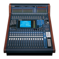
DM2000
Bottom Assembly
5. CPU Circuit Board
(Time required: About 15 minutes)
5-1. Remove the SP2000. (See procedure 1.)
5-2. Remove the MB2000. (See procedure 2.)
5-3. Fasten the control panel assembly. (See procedure 3.)
5-4. Remove the five (5) screws marked [335]. The CPU
circuit board can then be removed. (Fig.4)
6. Replacing the Lithium Battery
(Time required: About 15 minutes)
6-1. Remove the SP2000. (See procedure 1.)
6-2. Remove the MB2000. (See procedure 2.)
6-3. Fasten the control panel assembly. (See procedure 3.)
6-4. You can replace the lithium battery from the CPU
circuit board. (Fig.4)
The lithium battery is not part of the CPU circuit
board. When you replace the CPU circuit
board, you should remove the lithium battery
from the board, and install in the holder on
the new circuit board.
7. DSP Circuit Board
(Time required: About 25 minutes)
7-1. Remove the SP2000. (See procedure 1.)
7-2. Remove the MB2000. (See procedure 2.)
7-3. Fasten the control panel assembly. (See procedure 3.)
7-4. Fasten the rear assembly U. (See procedure 4.)
7-5. Remove the CPU circuit board. (See procedure 5.)
7-6. Remove the seven (7) screws marked [310] and the
five (5) hexagonal spacers. The DSP circuit board
can then be removed. (Fig.3)
8. BRG Circuit Board
(Time required: About 20 minutes)
8-1. Remove the SP2000. (See procedure 1.)
8-2. Remove the MB2000. (See procedure 2.)
8-3. Fasten the control panel assembly. (See procedure 3.)
8-4. Fasten the rear assembly U. (See procedure 4.)
8-5. Remove the six (6) screws marked [290A]. The BRG
circuit board can then be removed. (Fig.3)
9. Power Supply Unit
(Time required: About 20 minutes)
9-1. Remove the SP2000. (See procedure 1.)
9-2. Remove the MB2000. (See procedure 2.)
9-3. Fasten the control panel assembly. (See procedure 3.)
9-4. Fasten the rear assembly U. (See procedure 4.)
9-5. Remove the eight (8) screws marked [255]. The
power supply unit can then be removed. (Fig.3)
Noise will be generated if a bundle of cables for
VOLUME is routed over the power supply unit,
so make sure it is routed as shown in Photo 6.
Never route as shown in Photo 7. (Photo.6, 7)
 Loading...