A
1
2
3
4
5
6
7
8
9
10
BCDEFGH I JK
L MN
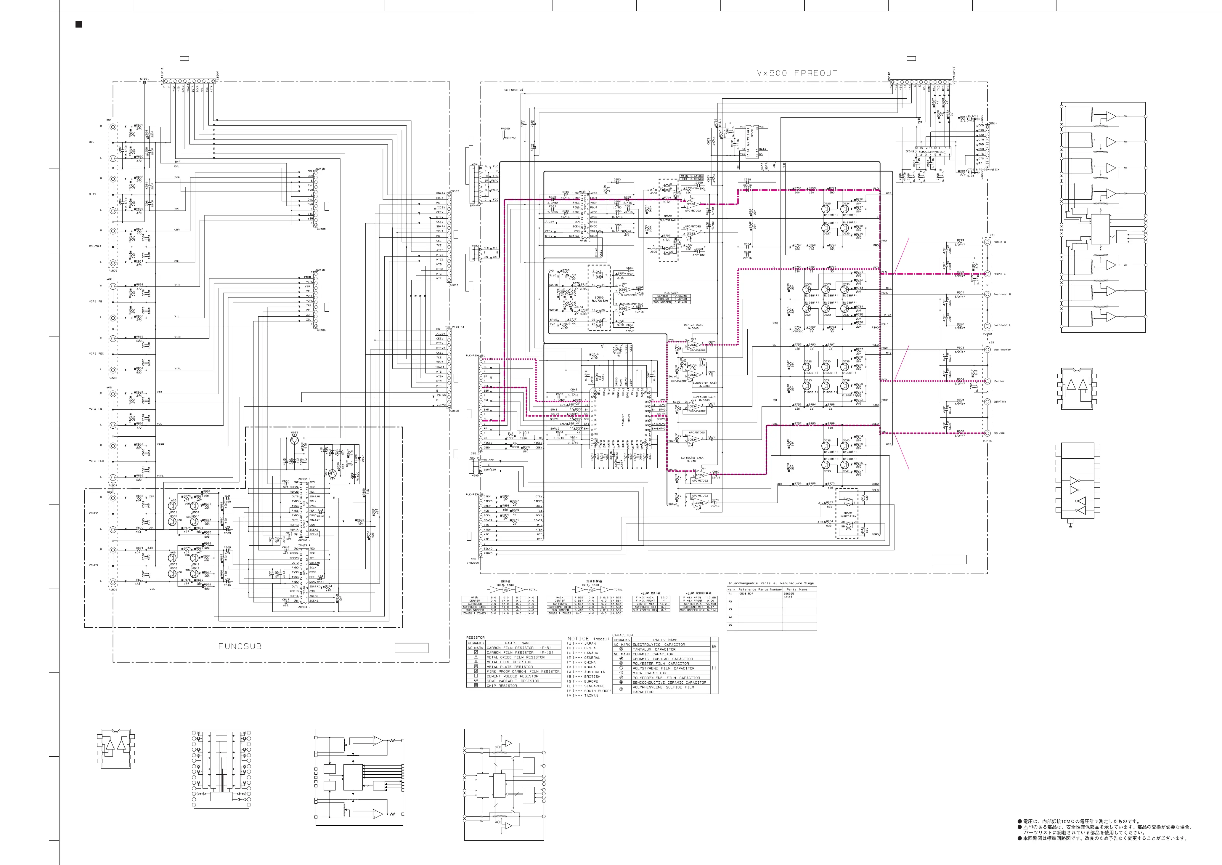
RX-V2500/DSP-AX2500
SCHEMATIC DIAGRAM (FUNCTION 1/2)
73
★ All voltages are measured with a 10MΩ/V DC electronic volt meter.
★ Components having special characteristics are marked s and must be replaced
with parts having specifications equal to those originally installed.
★ Schematic diagram is subject to change without notice.
FRONT L
SURROUND BACK L
CENTER
0
0
0
0
0
2.6
2.6
2.6
2.6
2.4
2.6
2.6
5.1
5.1
0
0
0
0.1
5.1
5.0
0
0
0
0
-11.9
11.7
0
0
0
11.7
0
0
0
-11.9
0
0
0
0
0
0
0
0
0
0
0
0
11.7
0
0
0
0
0
0
0
0
0
-11.9
0
-6.1
-6.1
6.2
6.2
0
0
0
0
0
0
0
0
0
0
0
0
0
0
0
0
0
0
0
0
0
0
0
0
0
6.2
6.2
-6.1
0
0
0
5.0
0.1
0
0
0
0
0
0
0
0
0
0
0
0
11.7
0
0
0
0
0
0
0
0
0
0
0
-11.9
-11.9
0
11.7
11.7
0
0
0
0
0
-11.9
0.1
0
-11.9
0.1
0
-11.9
0.1
0.1
0
0
0
0
0
0
0
0
-11.9
-11.9
0.1
0
0.1
0
-11.9
-11.9
0.1
0
0.1
0
-11.9
-11.9
-0.1
0
-0.1
0
-11.9
-11.9
-0.1
0
-0.1
0
-11.9
-11.9
0.1
0
-11.9
0.1
0
-11.9
0.1
0
-11.9
0
0.1
-11.9
0
0.1
-11.9
0
0.1
-11.9
0
0.1
-11.9
0
-0.1
-11.9
0
0
0
0
0
7.5
0.1
0
5.1
0.1
0.1
0
5.1
5.1
5.1
-9.1
EVR2
ZONE2/ZONE3 : U, C, A, B, G models only
S61
S62S62
S63
S54
S54
S54
S54
S54
S54
J510
S58
J511
S58
S56 S57
S59 S60
Page 74
to FUNCTION (3) – C-F_CNCT – CB533
E2
Page 74
to FUNCTION (5) – FI-FS_CNCT – CB518
B8Page74
to FUNCTION (5) – FI-FS_CNCT – CB519
B8
Page 74
to FUNCTION (3) – C-F_CNCT – CB523
A2
232C CONTROL
Page 77
to POWER (1)_CB40_#6
A4Page 80
to CONTROL_CB517_#27
H8
Page 74
to FUNCTION (4) – F_CNCT – CB543
J5Page 74
to FUNCTION (4) – F_CNCT – CB544
J6
Page 80
to CONTROL_CB509
I6Page 74
to FUNCTION (4) – F_CNCT – CB551
L6Page 77
to POWER (6)_CB44_#21
D2
IC505: NJU7311AM
Analog Function Switch
IC358, 532-534: µPC4570G2
Dual OP-Amp
IC530: NJM2068MD-TE2
Dual OP-Amp
IC515, 516: YAC526-EZE2 IC528: YAC520-EE2
Stereo Digital Volume Controller
IC529: YAC523-EVR2
Digital Volume
IC542: ADM202JRN-REEL7
RS-232 Driver/Receiver
–+
OUT1
–IN1
–VCC
+VCC
OUT2
1
2
3
4
5
+IN1 –IN2
+IN2
–+
6
7
8
12
LIN2
9
LOUT
8
VREF
VREF
VREF
256
256
Reset
Vref
Generator
&
Reset
pulse
Generator
2
SDATAO
20
SDATAI
19
CSN
1
SCLK
16
TE
18
ZCEN
S/P
Register
Control
Register
L
Zero Cross
Detection
11
LIN1
4
DVSS
3
DVDD
13
AVSS
6
AVDD
17
ICN
+
–
R
14
RIN2
7
ROUT
15
RIN1
+
–
16
3
IN1
34
OUT1
OUT2
VolB: 50kohm
VolA: 30kohm
45
TE1
44
TE2
39
ZCEN2
38
ZCEN1
2
AVDD
46
DGND
47
REF
1
AVSS
43
SDATAO (OD)
41
SDATAI
42
SCLK
40
20
19
18
CSN
Control
Register
25
REF1B
24
REF1A
0~95dB
100
0~+31.5dB
+
–
OPA
Zero Crossing
Detector
4
IN2
33
VolB: 50kohm
VolA: 30kohm
23
REF2B
22
REF2A
0~95dB
100
0~+31.5dB
+
–
OPA
Zero Crossing
Detector
Zero Crossing
Detector
5
IN3
32
OUT3
OUT4
VolB: 50kohm
VolA: 30kohm
21
REF3B
20
REF3A
0~95dB
100
0~+31.5dB
+
–
OPA
Zero Crossing
Detector
Zero Crossing
Detector
6
IN4
31
VolB: 50kohm
VolA: 30kohm
19
REF4B
18
REF4A
0~95dB
100
0~+31.5dB
CH1, 2, 3, 4 Control
56
+
–
OPA
Zero Crossing
Detector
Zero Crossing
Detector
S/P
Register
OUT5
14
REF6B
VolB: 50kohm
VolA: 30kohm
8
IN6
13
REF7A
0~95dB
100
0~+31.5dB
+
–
OPA
12
REF7B
OUT6
OUT7
VolB: 50kohm
VolA: 30kohm
9
IN7
15
REF6A
0~95dB
100
0~+31.5dB
+
–
OPA
16
REF5B
VolB: 50kohm
VolA: 30kohm
7
IN5
17
REF5A
0~95dB
100
0~+31.5dB
CH5, 6, 7 Control
+
–
OPA
1
3
2
16
C1+
C1–
Vcc
V+
11
14
T1in
T1out
+5V → +10V
Voltage Boost
Circuit
4
5
6
C2+
C2–
V–
+10V → –10V
Voltage Inverter
T1
10
7
T2in
T2out
T2
12
13
R1in
R1out
R1
9
8
15
R2in
R2out
GND
R2
L1
L2
L-COM1
L3
L4
L-COM2
L5
L6
L-COM3
L7
L-COM4
ST
V
DD
VEE
LEVEL SHIFTER
LATCH
LATCH
CONTROL
LEVEL SHIFTER
R1
R2
R-COM1
R3
R4
R-COM2
R5
R6
R-COM3
R7
R-COM4
DATA
CK
V
SS
2
3
4
5
6
7
8
9
10
11
12
13
28
1
27
26
25
24
23
22
21
20
19
18
17
16
15
14
FUNC (2)
FUNC (1)
–+
OUT1
–IN1
–VCC
+VCC
OUT2
1
2
3
4
5
+IN1 –IN2
+IN2
–+
6
7
8
IN1
OUT1
TE1
TE2
TE3
ZCEN1
ZCEN2
OUT2
24
22
23
5
6
7
14
15
13
16
3
8
4
9
2
1
12
11
10
21
REF1B
REF1A
REF2A
REF2B
IN2
AVDD
DGND
REF
AVSS
DVSS
SDATAO (Open Drain)
S DATA I
SCLK
CSN
Vol B: 10kΩ
0 ~ -95dB
0 ~ -95dB
0 ~ +31.5dB
16
0 ~ +31.5dB
OP Amp
Zero
Crossing
Detector
Zero
Crossing
Detector
S/P
Register
Control
Register
OP Amp
Vol B: 10kΩ
Vol A: 15kΩ
100Ω
100Ω
Vol A: 15kΩ
 Loading...