DSP-AX620
DSP-AX620
22
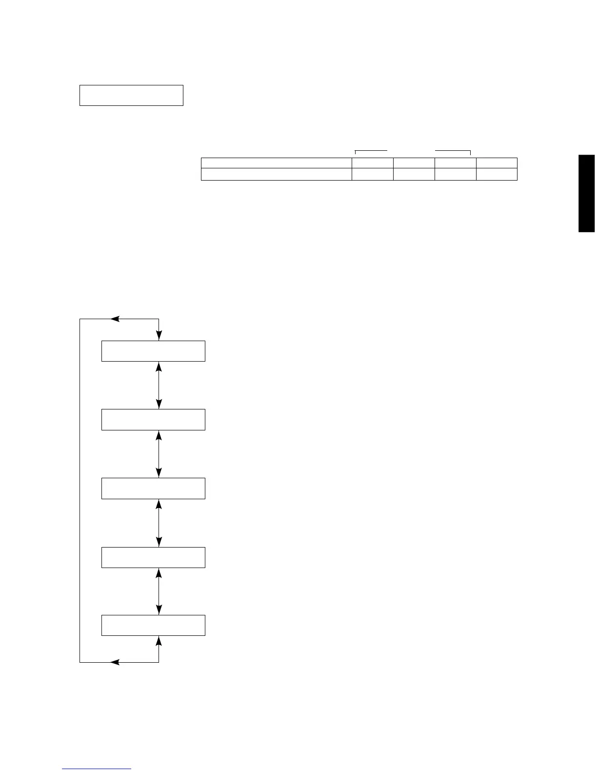
8. DISPLAY CHECK
• This program is used to check the lighting of the FL display which changes as shown below according to the sub-
menu selected.
• The signals are processed using EFFECT OFF. (The L/R signals are output using the ANALOG MAIN BYPASS
setting.)
• Except for the initial display, 128 pictographs for checking the OSD driver are used for the video signal
output display (monitor screen).
Segment conditions of the FL driver (IC502) and
the FL tube are checked by turning ON and OFF
all segments. Next, the operation of the FL driver
is checked by using the dimmer control. Then a
short between segments next to each other is
checked by turning ON and OFF all segments
alternately (in a lattice).
All segments OFF
(Initial display)
[Remote control code: 7A—01 (TAPE RW)]
All segments ON
(dimmer 100%)
[Remote control code: 7A—02 (TAPE FW)]
All segments ON
(dimmer 50%)
[Remote control code: ––––]
Lighting of segments
in a lattice 1
[Remote control code: ––––]
Lighting of segments
in a lattice 2
[Remote control code: ––––]
7. OTHER INPUT
The signal input through the 6CH INPUT terminals is output.
7.EXTERNAL DEC
EXTERNAL DEC [Remote control code: 7A—8F (PRG 8)]
Condition
Both ch, -26 dBV, volume 0dB
MAIN L/R
19.5 dBV
CENTER
19.5 dBV
REAR L/R
19.5 dBV
SWFR
- 3.5 dBV
Reference
INPUT : 6CH INPUT
SWFR: 50Hz, Others: 1kHz
SPEAKERS

 Loading...