DSP-AX620
DSP-AX620
8
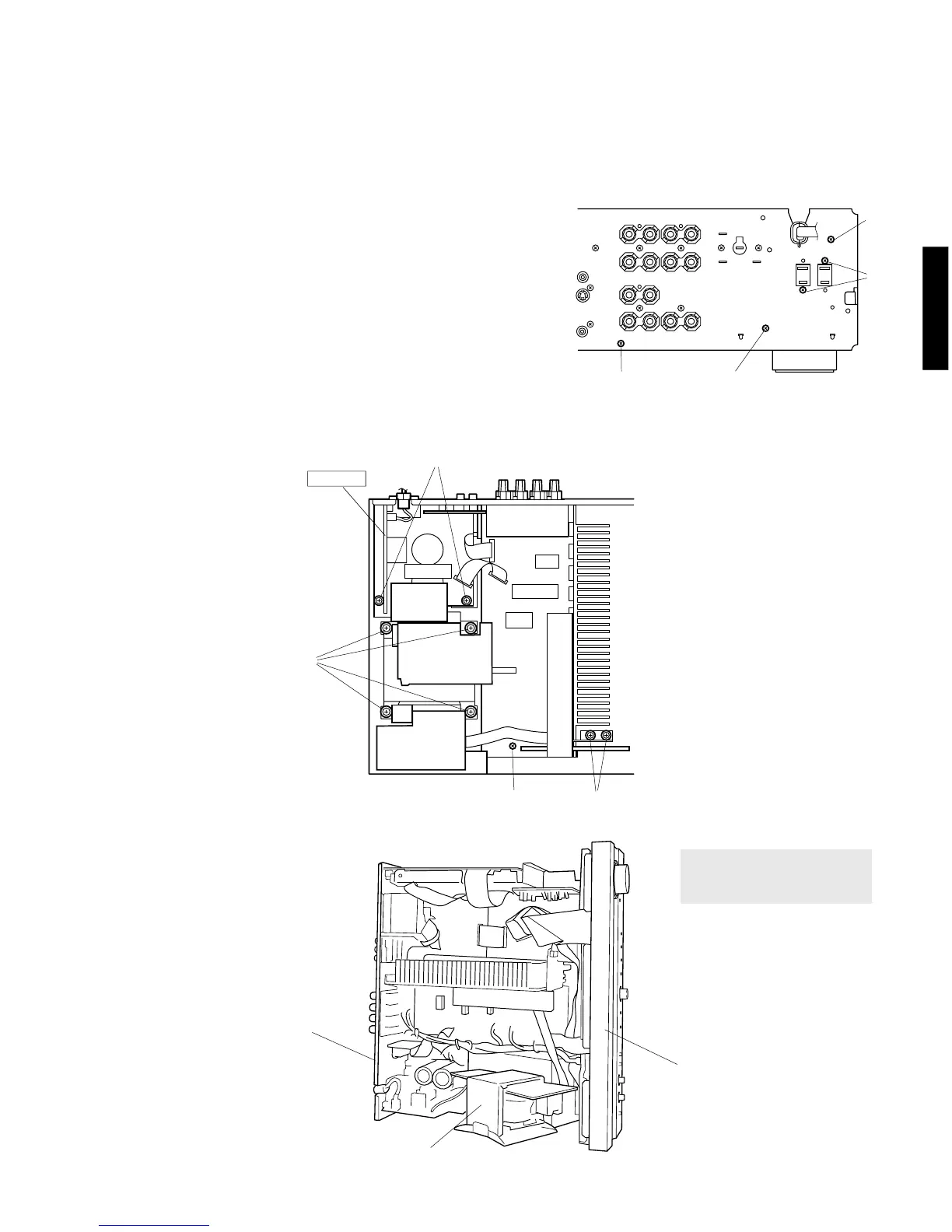
6. Removal of Main Chassis
(Checking the Main (1) P.C.B. and Replacing Components)
a. Remove the Front Panel Unit.
b. Remove the Sub Chassis Unit.
c. Remove the DSP P.C.B.
Fig. 7
Fig.8
Fig.9
d. Remove the Input (4) P.C.B, Operation (5)/(3)/(2) P.C.B.
and Input (1)/(2) P.C.B.
e. Remove 6 screws ( !7, !8 and !9 ) and then remove the
Main (5)/Power (1) P.C.B. in Fig. 7 and 8.
f. Remove 4 screws ( @0 ) and then remove the Power
Transformer in Fig. 8.
g. Remove 4 screws ( @1, @2 and @3 ) and then remove the
Main Chassis in Fig. 7 and 8.
h. Reinstall the removed P.C.B. to the Rear Panel and tighten
them with screws.
i. Set the Rear Panel and Front Panel upright as shown in Fig.
9. At this time, use a box or the like to keep them horizontal.
In this state, check the MAIN (1) P.C.B. and each of the
other P.C.B. for operation.
@3
!8
!7
!8
Power Transformer
Rear Panel
Front Panel
MAIN (1)
MAIN (5)
POWER (1)
!9
@0
@1
@2
Use care so that the DSP Shield
Case and INPUT (1)/(2) P.C.B.
will not be shorted.

 Loading...