DSP-AX620
DSP-AX620
24
11. AD DATA
The sub-menu of this menu displays the A/D conversion value of the CPU (operation circuit board IC501) which
detects the keys and protection functions of the main unit in %. (reference voltage 5V: 100%)
When in KY0/KY1/KY2 page, it is not possible to operate the keys of the main unit because the values of all keys
are detected. But one click on the VOLUME of the main unit will cancel this function and sets to the next sub-menu.
The signal processing state remains the same as that before executing this menu.
The above figures are ex-
amples for reference.
DC/PS (Detection of the protection function) [Remote control code: 7A—0B (CD SKIP –)]
DC: Protection value for DC detection (Normal value: 1~13)
0.05V~ 0.65V (reference voltage)
When the value is out of the normal value range, the protection function works to turn
off the power.
PS: Protection value for power voltage (Normal value: 23~37)
1.15V~ 1.85V (reference voltage)
When the value is out of the normal value range, the protection function works to turn
off the power.
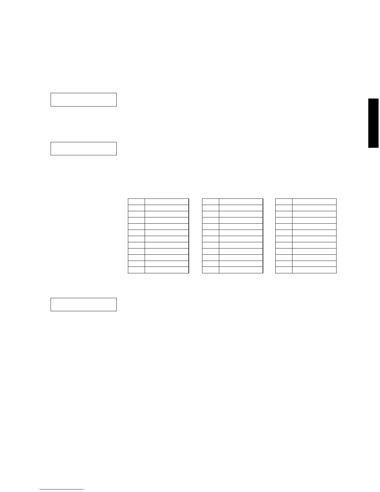
KY0/KY1 (Detection of key scan)[Remote control code: ––––]
KY0/KY1: Panel key of the main unit (10% step)
Indicate
KY0
0 –
10 –
20 –
30 –
40 –
50 –
60 –
70 –
80 –
90 –
100 KEY OFF state
Indicate
KY1
0 SET MENU
10 DSP PROGRAM
20 EFFECT
30 –
40 –
50 –
60 –
70 –
80 –
90 –
100 KEY OFF state
Indicate
KY2
0 INPUT MODE
10 INPUT q
20 INPUT w
30 6CH INPUT
40 –
50 –
60 –
70 –
80 –
90 –
100 KEY OFF state
KY2/PL (Detection of key scan/Power limit)[Remote control code: ––––]
KY2: Panel key of the main unit (10% step)
PL: The value of the power limit (10% step)
K0:100 K1:100
K2:100 PL:020
DC:007 PS:025
• When the standard value is deviated by ±4%, KEY A/D fails to function properly. In this case,
check the circuit voltages, soldering condition, etc.

 Loading...