DSP-AX620
DSP-AX620
37
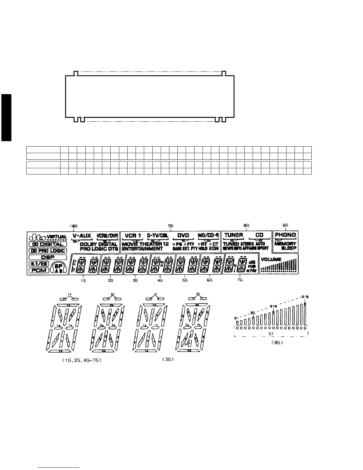
■ DISPLAY DATA
V501 : 10-BT-236GNK (V6785800)
PATTERN AREA
q%5
● GRID ASSIGNMENT
Note 1) F1, F2 ......... Filament
2) NP .............. No Pin
3) NC .............. No Connction
4) P1~P35....... Datum Line
● PIN CONNECTION
Pin No. 123456789101112131415161718192021222324252627282930
Connection F1 F1 NP NP P1 P2 P3 P4 P5 P6 P7 P8 P9 P10 P11 P12 P13 P14 P15 P16 P17 P18 P19 P20 P21 P22 P23 P24 P25 P26
Pin No. 31 32 33 34 35 36 37 38 39 40 41 42 43 44 45 46 47 48 49 50 51 52 53 54 55
Connection P27 P28 P29 P30 P31 P32 P33 P34 P35 NC NC 10G 9G 8G 7G 6G 5G 4G 3G 2G 1G NP NP F2 F2
5) 1G~8G ........ Grid

 Loading...