DSP-AX620
DSP-AX620
27
14. VERSION/SUM
There are two sub-menu items.
Indicates the program version, checksum of the microprocessor (IC501 of the operation circuit board).
The checksum is obtained by adding data for every 8 bits for each program area and expressing the
result as a 4-figure hexadecimal data.
The signals are processed using EFFECT OFF. (The L/R signals are output using ANALOG MAIN
BYPASS setting.)
A: All
P: Program area
Version [Remote control code: 7A—0D (CD REW)]
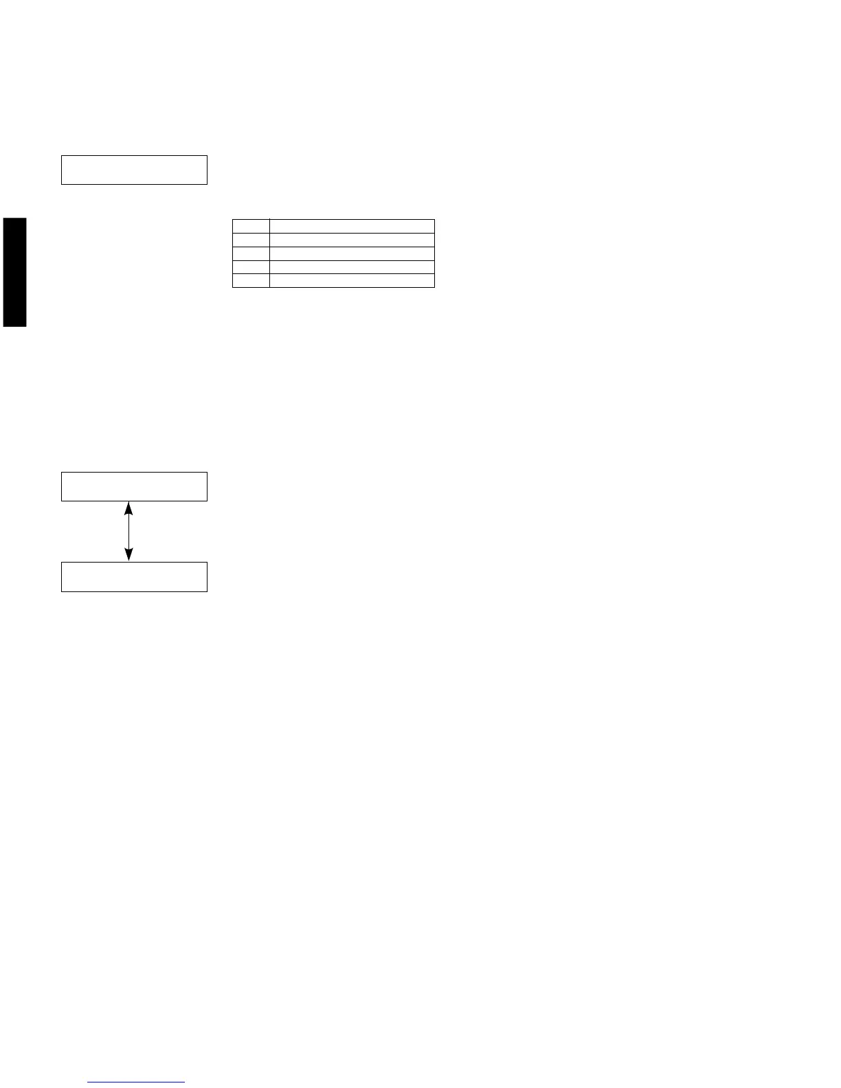
13. DSP RAM CHECK [Remote control code: 7A—0A (CD SKIP +)]
This menu is used to self-diagnose whether or not YSS928 (IC801 of DSP circuit board) and external
RAM (IC802 of DSP circuit board) are connected properly.
During signal processing, the status before execution of this menu is maintained.
Checks the address bus and the data bus, and indicates the connection condi-
tion.
“NOER” appears when no error is detected.
Indicate
Function
WAIT
Bus being checked
NOER
No error detected
DATA
Short or open of data bus
ADDR
Short or open of address bus
Checksum [Remote control code: ––––]
Release 1 figure / Main 2 figures / DSP 2 figures
BUS CHECK:NOER
VER. XXXXX
A:XXXX P:XXXX

 Loading...