DSP-AX620
DSP-AX620
7
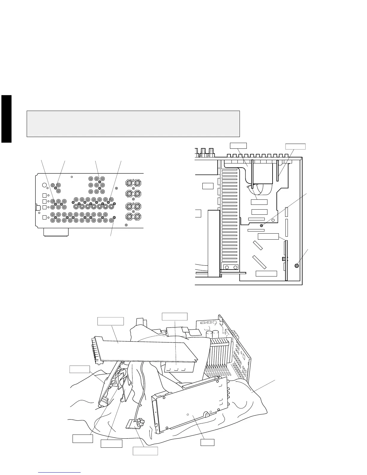
5. Removal of Input (1)/(2) P.C.B.
(Checking the Input (1)/(2) P.C.B. and Replacing Components)
a. Remove the DSP P.C.B.
b. Remove 1 screw ( !0 ) and then remove the Input (4) P.C.B. in Fig. 4.
c. Remove 2 screws ( !1 ) and then remove the Operation (5) P.C.B. in Fig. 4.
d. Remove 4 screws ( !2 ) and then remove the Operation (3) P.C.B. in Fig. 4.
e. Remove 7 screws ( !3 and !4 ) and then remove the Operation (2) P.C.B. in Fig. 4
and 5.
f. Remove 8 screws ( !5 and ! 6 ) and then remove the Input (1)/(2) P.C.B. in Fig. 4
and 5.
g. Place the INPUT (1)/(2) P.C.B. as shown in Fig. 6 and check them for operation.
Note :
When DSP P.C.B., INPUT (1)/(4) P.C.B., OPE (2)/(3) P.C.B., and OPE (5) P.C.B. have been
removed from the rear panel, the ground connection becomes open. Connect the ground of
each P.C.B. to the chassis by using a lead wire.
Fig. 4
Fig. 5
Fig.6
INPUT (4)
INPUT (1)
INPUT (2)
OPE (2)
OPE (5)
OPE (3)
INPUT (1)
INPUT (2)
OPE (2)
OPE (5)
OPE (3)
INPUT (4)
DSP
!3x6 !0 !1x2 !2x4
!5x7
!4
!6
Cloth
 Loading...


