DTX900 Owner’s Manual
57
Drum Kit mode
Reference
Song modeClick modeTr igger modeFile modeUtility modeChain modeSampling mode
Reference
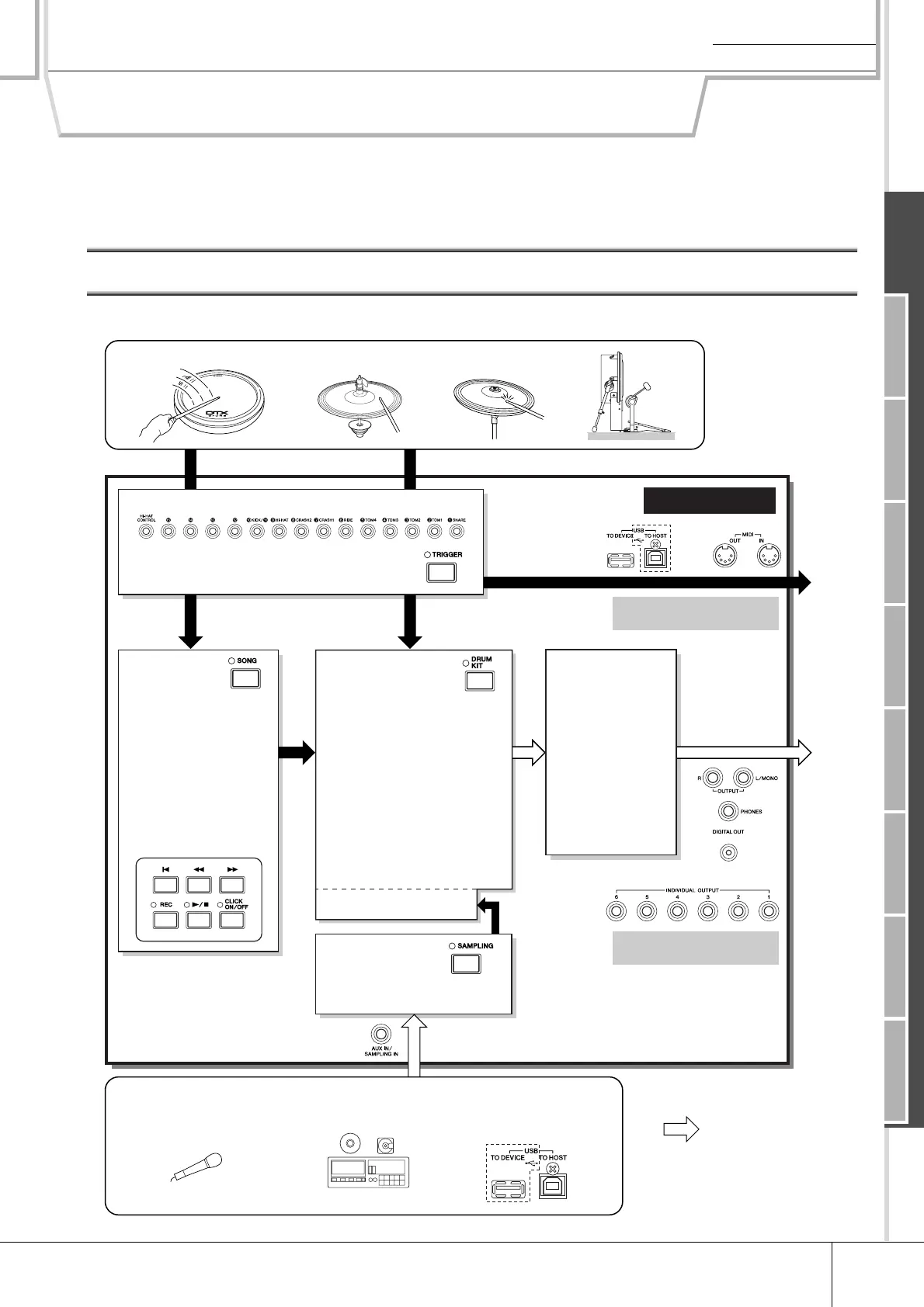
Basic Structure of the DTX900
This section describes the internal design of the DTX900 so that you can fully take advantage of the advanced and con-
venient functions of this instrument. Take a few moments here to understand how trigger signals are generated and
transferred to the DTX900 when you hit the pads and how the sound is produced.
The Functional Blocks
Pad (Trigger Input Source)
Tr igger Signal
Trigger Input jacks
● Trigger Setup
• Preset
• User
Recording your drum perfor-
mance as MIDI data.
Playing the tone generator by
hitting the pad.
or
or
MIDI
output
Audio
output
Tone Generator
● Drum Kit
Created by assigning a Drum
Voice to each of the Trigger
Input Sources on the pad. The
following banks are available.
• Preset Drum Kit
• User Drum Kit
• External Drum Kit A – P
● Drum Voice
Assigned to each Trigger Input
Source of the pad to make up
a Drum Kit.
• Preset Voice
• User Voice
Sampling
Assigns the audio
signal (obtained from the
external device) to a User Voice.
Audio signal
Recording the audio signal from the external audio device or microphone
in the Sampling mode, or loading the audio file from the USB storage
device in the File mode.
Effect
● Set for each
Drum Kit
• Reverb
• Chorus
• Variation
● Set in the Utility
mode
• Master Effect
• Master EQ
Song
● Playback
• Preset Song
• User Song
• External Song
● Recording
Recording your drum
performance to a User
Song as MIDI data.
Playback
[DRUM KIT] → [F2] VOICE →
[SF2] OUT-TUNE → OutputSel
[UTILITY] → [F5] MIDI → [SF3]
OTHER → MIDI IN/OUT
Microphone, etc.
CD, MD, etc.
Tr igger Signal
DTX900