HOW TO USE THIS MANUAL
This manual is intended as a handy, easy-to-read reference book for the mechanic.
Comprehensive explanations of all installation, removal, disassembly, assembly, repair and check
procedures are laid out with the individual steps in sequential order.
• The manual is divided into chapters and each chapter is divided into sections. The current section
title is shown at the top of each page “1”.
• Sub-section titles appear in smaller print than the section title “2”.
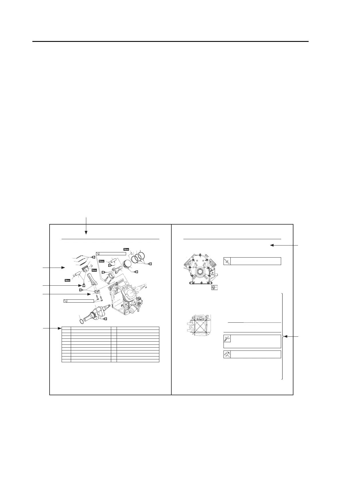
• To help identify parts and clarify procedure steps, there are exploded diagrams at the start of each
removal and disassembly section “3”.
• Numbers are given in the order of the jobs in the exploded diagram. A number indicates a disas-
sembly step “4”.
• Symbols indicate parts to be lubricated or replaced “5”. Refer to “SYMBOLS”.
• A job instruction chart accompanies the exploded diagram, providing the order of jobs, names of
parts, notes in jobs, etc. “6”. This step explains removal procedure only. For installation, reverse
the steps.
• Jobs requiring more information (such as special tools and technical data) are described sequen-
tially “7”.
PISTONS, CAMSHAFT, CRANKCASE, AND CRANKSHAFT
3-46
PISTONS AND CRANKSHAFT
Order Job/Parts to remove Q’ty Remarks
Removing the pistons and crankshaft Remove the parts in the order listed.
2pac dor gnitcennoC1
1tfahsknarC2
1mihs tfahsknarC3
2dor gnitcennoC4
4pilcric nip notsiP5
2nip notsiP6
2
notsiP7
gnir poT2gnir notsiP8
gnir dn22gnir notsiP9
gnir liO2gnir notsiP01
1
2
3
4
5
6
7
8
9
10
5
5
7
10
9
8
5
6
1
25 N・m (2.5 kgf・m, 18 lb・ft)
25 N・m (2.5 kgf・m, 18 lb・ft)
4
PISTONS, CAMSHAFT, CRANKCASE, AND CRANKSHAFT
3-54
INSTALLING THE CRANKCASE COVER
1.
Install:
• Crankcase cover
• Crankcase cover bolts “1”–“10”
CHECKING THE CYLINDERS AND PISTONS
1.
Check:
• Piston wall
• Cylinder wall
Vertical scratches → Replace the cylinder, and
replace the piston and piston rings as a set.
2.
Measure:
• Cylinder warpage
Measure the warpage on the contact surface of the cylin-
der head at six points using a straight edge and thickness
gauge.
Out of specification → Replace the crankcase
assembly.
3.
Measure:
• Piston-to-cylinder clearance
a. Measure the cylinder bore “C” with the cylinder
bore gauge.
Crankcase cover bolt:
25 N·m (2.5 kgf·m, 18 lb·ft)
Thickness gauge:
90890-03268
Feeler gauge set:
YU-26900-9
Warpage limit:
0.1 mm (0.0039 in)
1
7
2
6
3
4
5
 Loading...