7-9
Power unit
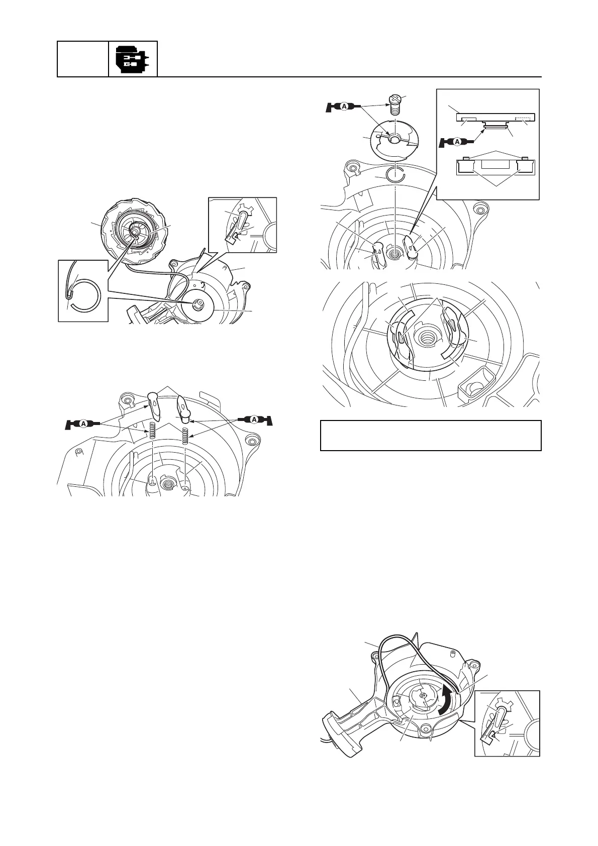
8. Install the sheave drum f with the
protrusion g on the starter plunger b
and the mark h of the manual starter i
aligned.
9. Turn the sheave drum f to hook the end
k of the spiral spring g onto the section
m in the manual starter i.
10. Install the drive pawl springs j and drive
pawls k.
11. Install the clip l to the drive plate m.
12. Install the drive plate m by aligning the
protrusion n on the drive pawls k and
the slots p in the drive plate m, and then
tighten the drive plate screw n to the
specified torque.
13. Align the protrusion g on the starter
plunger b and the mark h on the
manual starter i.
14. While holding the starter rope e, turn the
sheave dram f 3 turns counterclock-
wise.
15. Remove the starter rope e from the slot
d, and then let the sheave drum f turn
slowly so that the starter rope e is
wound around the sheave drum f.
k
f
h
i
m
h
b
g
g
j
k
Drive plate screw n:
7 N·m (0.7 kgf·m, 5.2 ft·lb)
l
m
l
m
n
k
k
k
pp
n
n
n
np
p
m
k
k