9-14
Upper case and shift lever
0
1
2
3
4
5
6
7
8
9
10
A
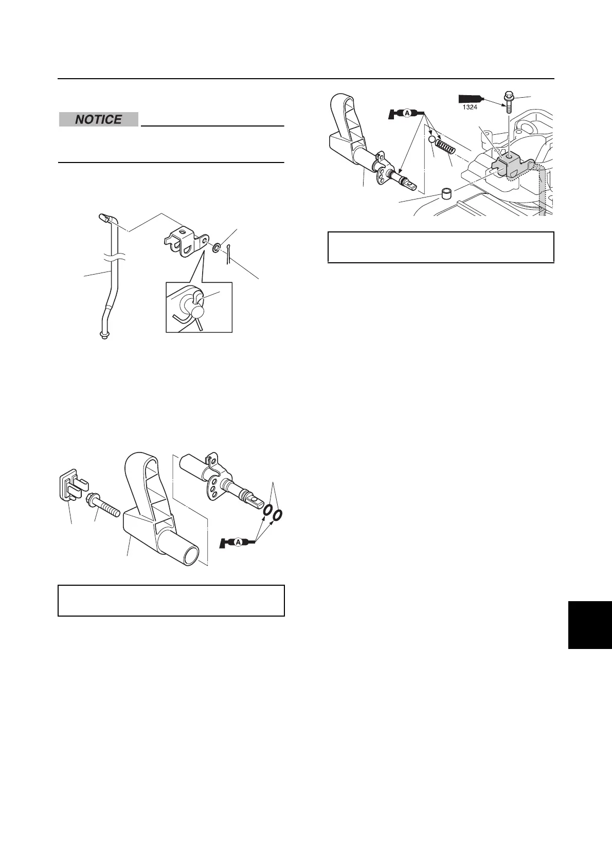
Installing the shift lever
Do not reuse a cotter pin or O-ring, always
replace it with a new one.
1. Install the shift rod a, the washer b, and
a new cotter pin c.
2. Install new O-rings d and the shift lever
e.
3. Tighten the shift lever bolt f to the
specified torque, and then install the cap
g.
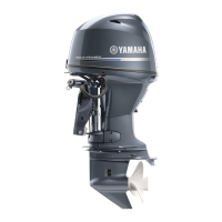
4. Install the spring h, ball i, collar j,
bracket k, and shift lever e.
5. Tighten the shift link bolt l to the
specified torque.
Shift lever bolt f:
19 N·m (1.9 kgf·m, 14.0 ft·lb)
d
f
g
e
Shift link bolt l:
3.5 N·m (0.35 kgf·m, 2.58 ft·lb)
i
e
l
k
h
j