7-34
Cylinder head
0
1
2
3
4
5
6
7
8
9
10
A
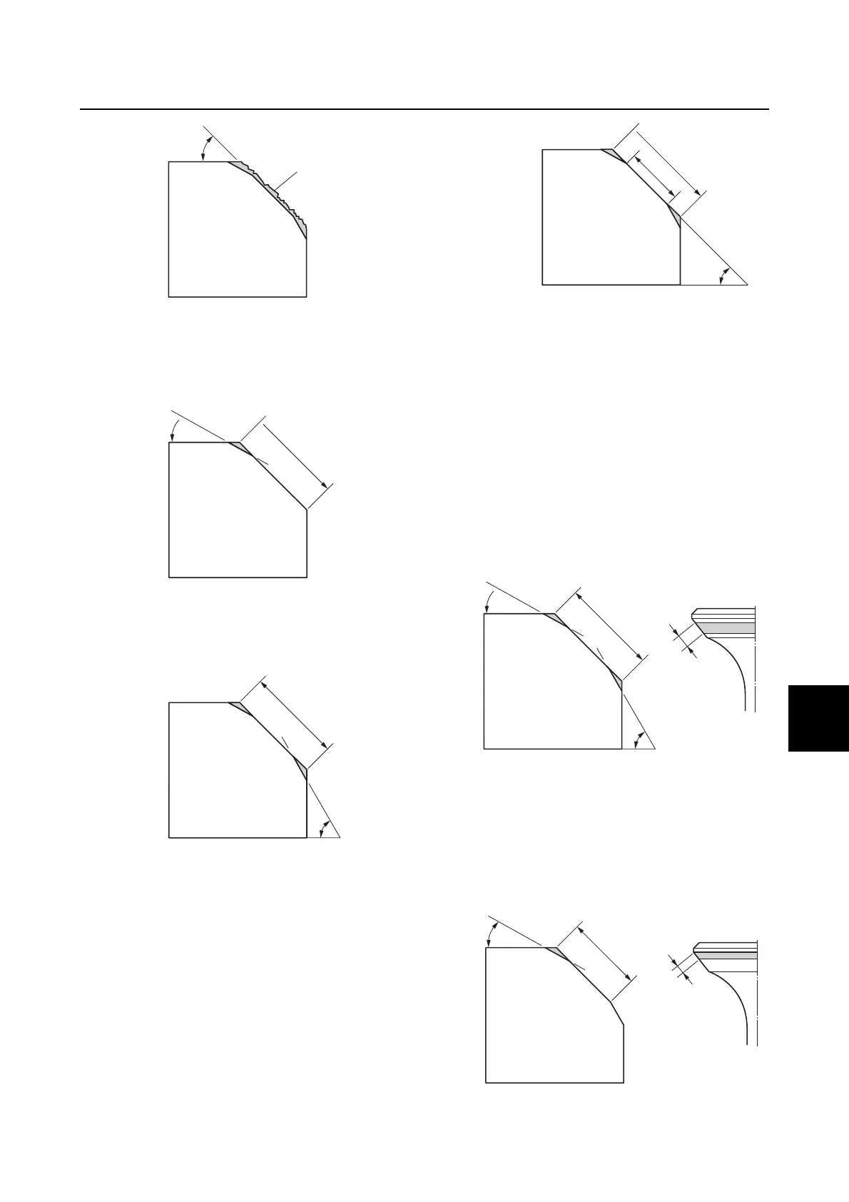
a Slag or rough surface
3. Adjust the top edge of the valve seat
contact width using a 30° cutter.
b Previous contact width
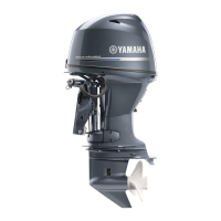
4. Adjust the bottom edge of the valve seat
contact width using a 60° cutter.
b Previous contact width
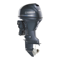
5. Adjust the valve seat contact width to
specification using a 45° cutter.
b Previous contact width
c Specified contact width
6. Check the valve seat contact area of the
valve. See “Checking the valve seat” (7-
32).
Example:
• If the valve seat contact area is too wide
and situated in the center of the valve face,
cut the top edge of the valve seat using a
30° cutter, and then cut the bottom edge
using a 60° cutter to center the area and set
its width.
b Previous contact width
• If the valve seat contact area is too narrow
and situated near the top edge of the valve
face, cut the top edge of the valve seat
using a 30° cutter to center the area, and
then set its width using a 45° cutter.
b Previous contact width
a
45˚
b
30˚
b
60˚
45˚
b
c
30˚
60˚
b
30˚
b