7-47
Power unit
• Make sure that the “N” marks h of the 2nd
ring f and the top ring g are facing
upward.
• Make sure that the piston rings move
smoothly.
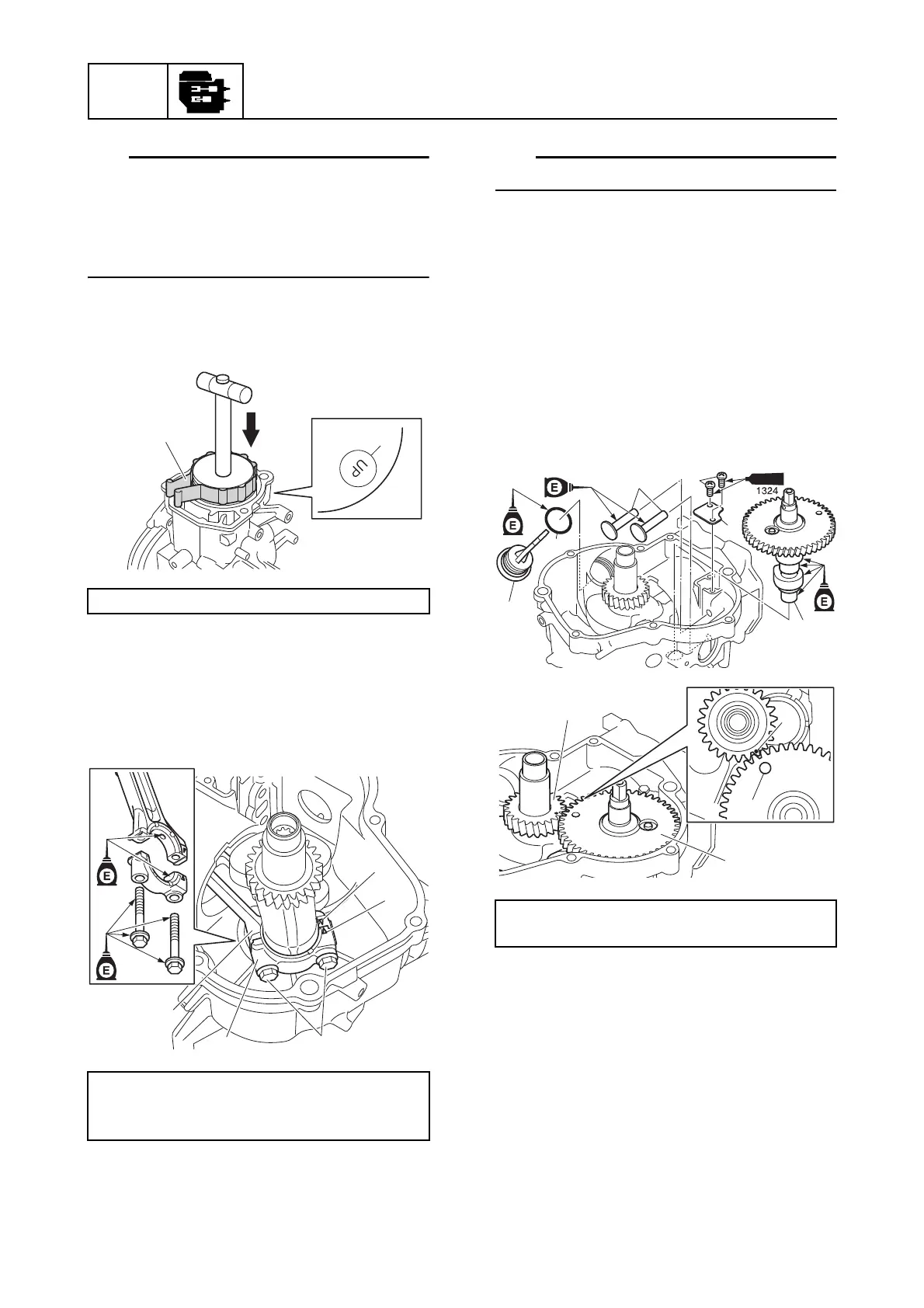
7. Install the piston with the “UP” mark c
on the piston crown facing toward the
flywheel magnet.
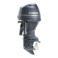
8. Install the connecting rod cap k by
aligning the mark m on the connecting
rod a and the mark n on the connecting
rod cap k, and then tighten the
connecting rod cap bolts m to the
specified torques in 2 stages.
Make sure that the crankshaft turns smoothly.
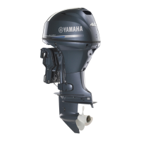
9. Install the valve lifters n.
10. Align the mark p on the crankshaft o
with the mark r on the camshaft p, and
then install the camshaft p.
11. Install a new O-ring q to the dipstick r,
and then screw in the dipstick r.
12. Install the plate s, and then tighten the
breather plate screws t to the specified
torque.
Piston slider l: 90890-06529
Connecting rod cap bolt m:
1st: 6 N·m (0.6 kgf·m, 4.4 ft·lb)
2nd: 12 N·m (1.2 kgf·m, 8.9 ft·lb)
n
m
k
m
a
Breather plate screw t:
8 N·m (0.8 kgf·m, 5.9 ft·lb)
p
r
p
o