6-18
Outboard Rigging Guide - 2001 30HP Tiller Handle Kit
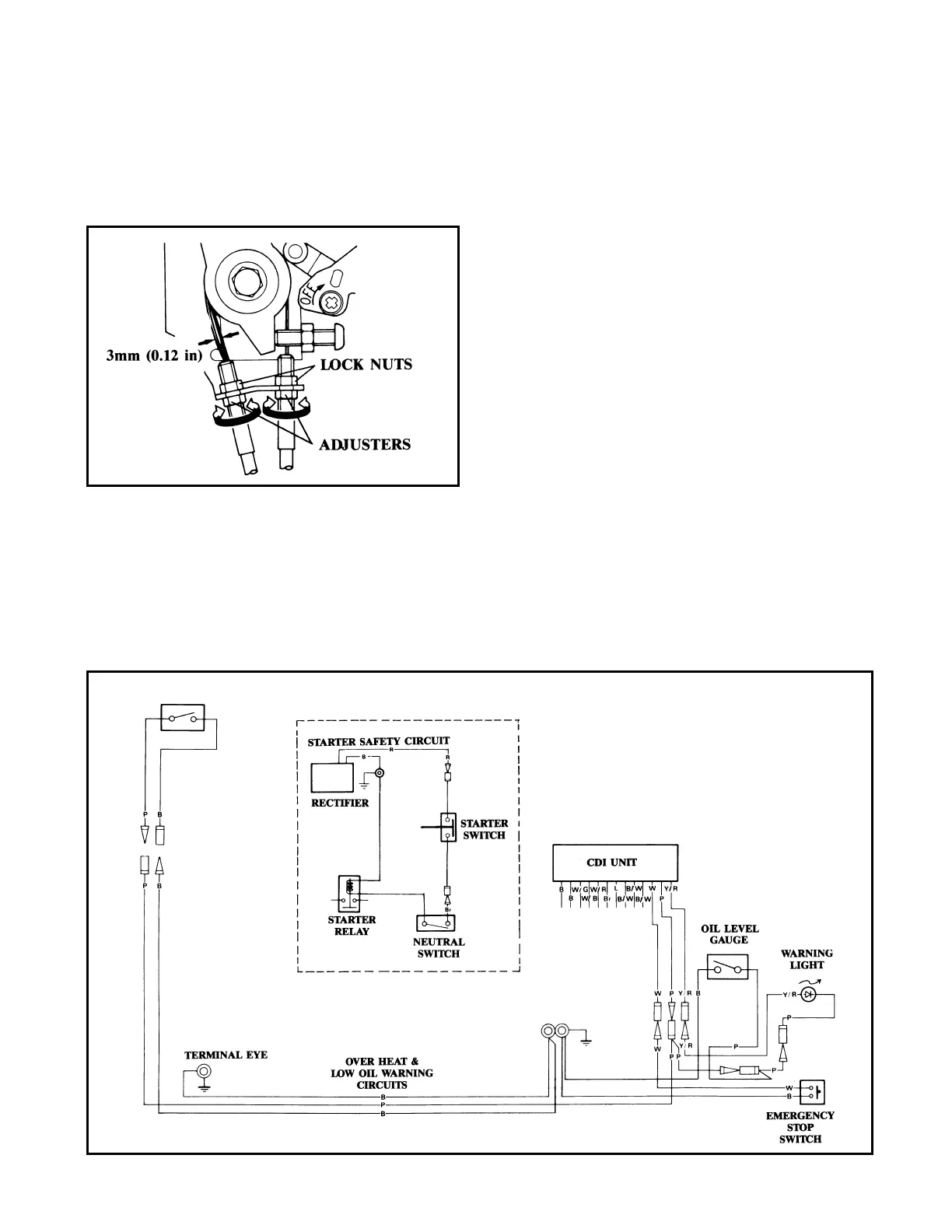
20. Loosen the lock nut on the “push” throttle
cable, adjust the cable adjuster until there is
3mm (0.12 in) slack in the inner cable (as
shown), and retighten the lock nut.
21. Remove the terminal cover (spare fuse is
attached), disconnect the main harness (com-
plete with plug), and remove it and the old
grommet from the motor.
NOTE: It will be easier if you disconnect the var-
ious wires as you are ready to install the new ones
as instructed below.
Do not tighten the bolts that retain the black
ground wires until the next instruction.
22. Locate the new pink/black wire lead set (Part
Number: 6J8-82531-00-00), and connect one
end of its pink lead to the connector that goes
to the pink thermoswitch wire at the back of
the motor.* There is a pink “T” lead remain-
ing to be connected near the CDI box.
Connect the pink wire leading from the CDI
box* and the pink lead that goes to the oil
level gauge (tank switch) and oil warning
light* to the pink “T” leads. Connect the sin-
gle black (ground) male butt connector lead
to the black thermoswitch wire. Install one of
the black leads with the ring terminal under
the appropriate cylinder head bolt*, and tight-
en the bolt to specification (1st torque -
1.5kg-cm [11 ft-lb.]); 2nd torque - 2.8kg-m
[20 ft-lb.]), Install the other ring-terminal
black lead under the head of the “ground”
bolt that is located behind the terminal cover.
*The same color wire lead in the harness you
removed in step 21 was disconnected at this point.
THERM OSW ITCH
 Loading...