Rear Panel 23
01V96 Version 2—Owner’s Manual
2
Control Surface & Rear Panel
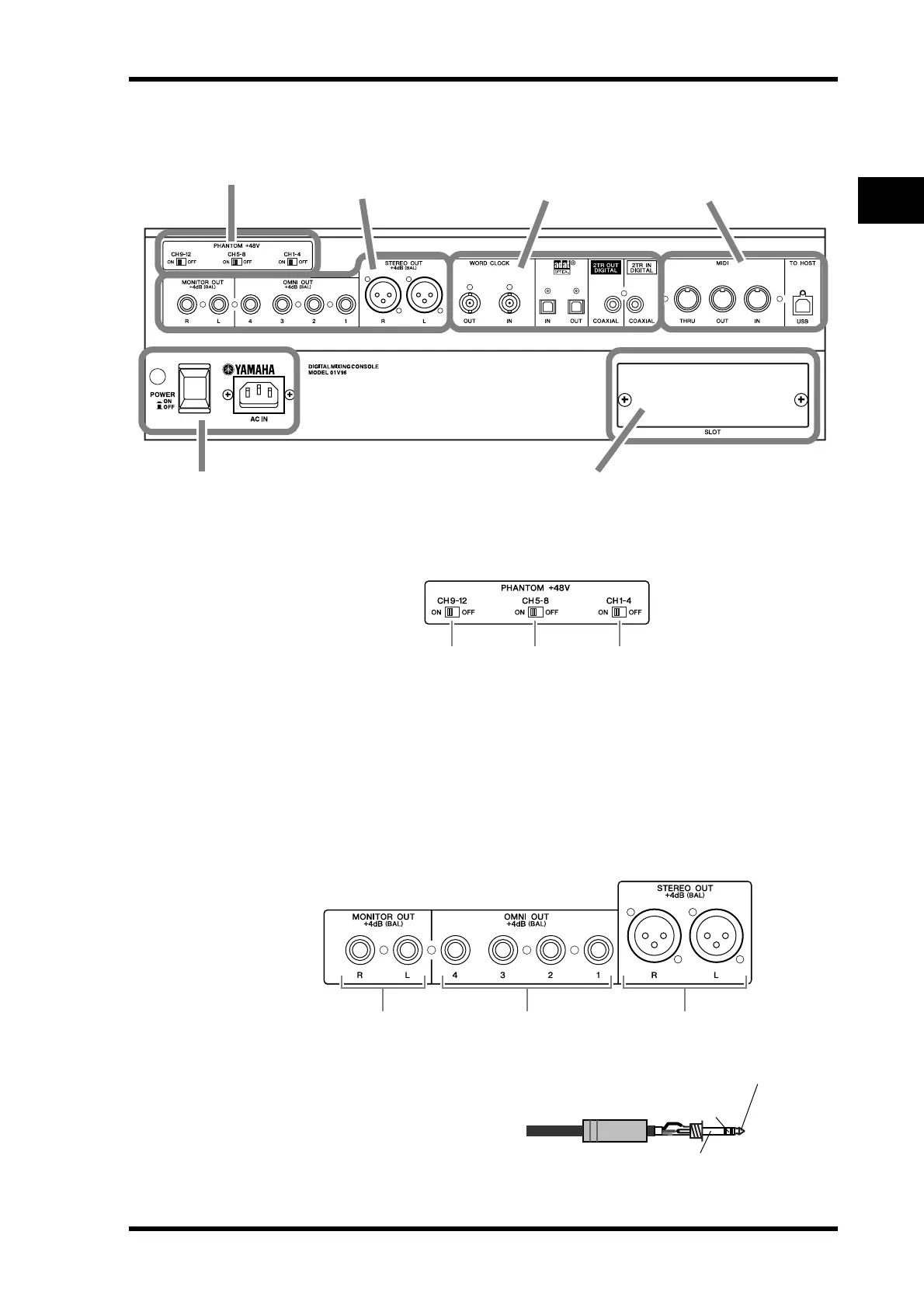
Rear Panel
PHANTOM +48V
A CH1–4 ON/OFF switch
B CH5–8 ON/OFF switch
C CH9–12 ON/OFF switch
Each of these switches turns on or off the +48V phantom power feed to four corresponding
inputs. When the switches are on, +48V phantom power is supplied to the INPUT A con-
nectors.
AD Output Section
A MONITOR OUT connectors L/R
These balanced TRS phone-type con-
nectors output monitoring signals or
2TR IN signals. The nominal signal
level is +4 dB.
You can select signals using the Mon-
itor Source selector.
PHANTOM +48V (p. 23)
Power Section (p. 25)
AD Output Section
(p. 23)
SLOT Section (p. 25)
MIDI/Control Section
(p. 25)
Digital I/O Section
(p. 24)
3 2 1
321
1/4" TRS phone plug
Ring
(cold)
Sleeve (ground)
Tip (hot)
 Loading...