24 Chapter 2—Control Surface & Rear Panel
01V96 Version 2—Owner’s Manual
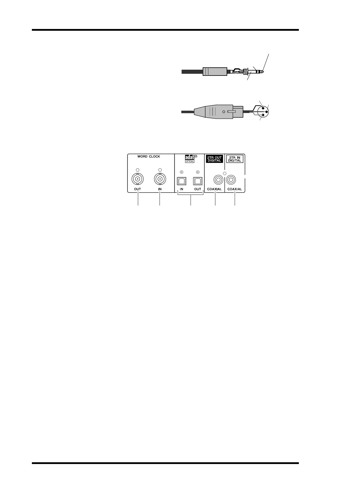
B OMNI OUT connectors 1–4
These balanced TRS phone-type con-
nectors output any Bus signals or
channel Direct Out signals. The nom-
inal signal level is +4 dB.
C STEREO OUT connectors L/R
These balanced XLR-3-32-type con-
nectors output the Stereo Out signals.
The nominal signal level is +4 dB.
Digital I/O Section
A WORD CLOCK OUT connector
This BNC connector outputs a wordclock signal from the 01V96 to a connected external
device.
B WORD CLOCK IN connector
This BNC connector inputs a wordclock signal from a connected external device to the
01V96.
C ADAT IN/OUT connectors
These optical TOSLINK connectors input and output ADAT digital audio signals.
D 2TR OUT DIGITAL COAXIAL
This RCA phono connector outputs consumer format (IEC-60958) digital audio. The con-
nector is typically used to connect the digital stereo input (consumer format) of a DAT
recorder, MD recorder, or CD recorder.
E 2TR IN DIGITAL COAXIAL
This RCA phono connector accepts consumer format (IEC-60958) digital audio. The con-
nector is typically used to connect the digital stereo output (consumer format) of a DAT
recorder, MD recorder, or CD recorder.
1/4" TRS phone plug
Ring
(cold)
Sleeve (ground)
Tip (hot)
Female XLR plug
1 (ground)
2 (hot)
3 (cold)
421 53
 Loading...