30
CHAPTER2 PROFIBUS Unit
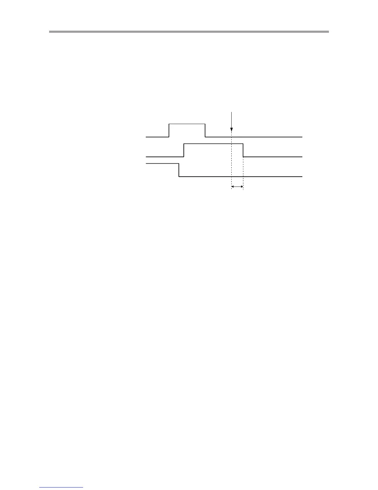
(4) When an on-going command becomes impossible to run
(In the following cases, END will not turn ON, when running of an on-going com-
mand becomes impossible.)
•When an interlock or emergency stop was triggered during running of a dedicated
command.
•When a jump to an unregistered program was made during automatic operation, a
move to an unregistered point was made or some kind of error occurred.
Dedicated
command
BUSY
END
Differs accordin
to execution command
Command execution impossible
(1) At the rise of the dedicated command input, the END signal turns off and the
BUSY signal turns on.
(2) Turns off (contact open) the dedicated command input after the BUSY signal
turns on.
(3) Wait until the BUSY signal turns off.
(4) The BUSY signal turns off because the command execution becomes impos-
sible before it is fully executed.
(5) The END signal remains off when the BUSY signal turns off, indicating that
the command could not end normally.