37
CHAPTER2 PROFIBUS Unit
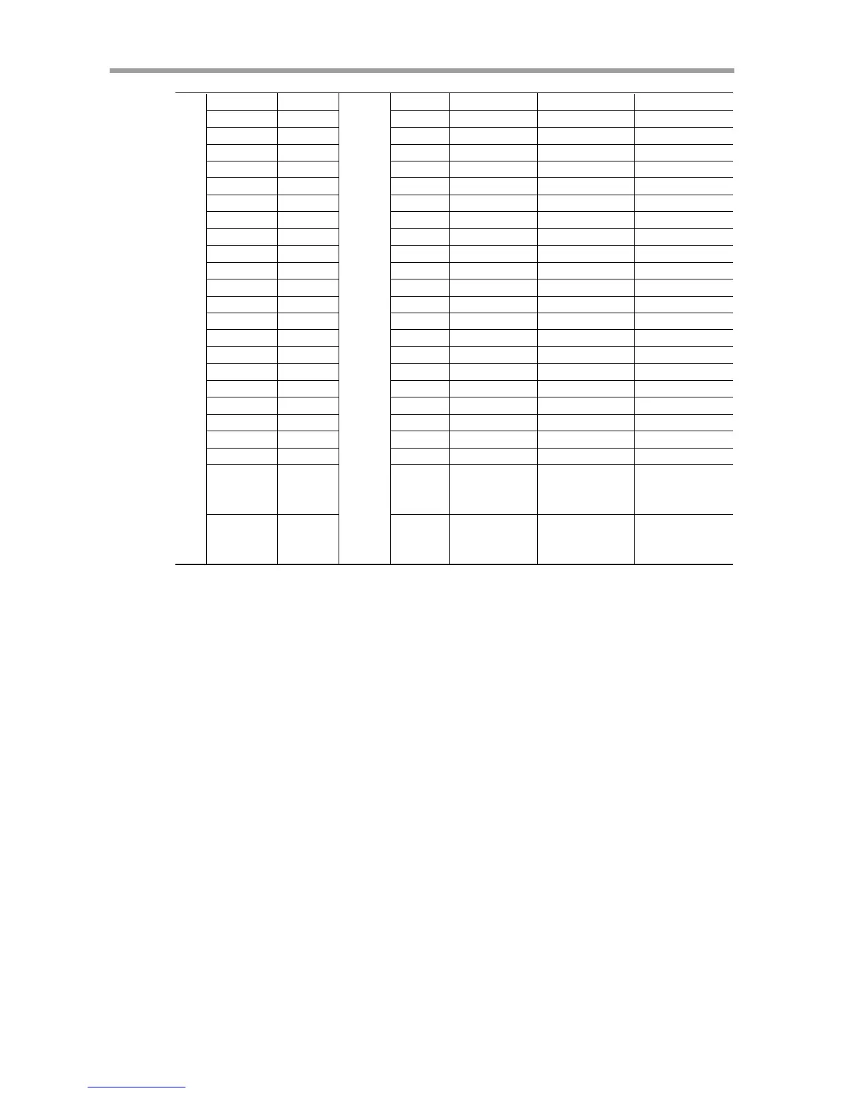
Output (Slave
→
Master)
Im.0
Im.1
Im.2
Im.3
Im.4
Im.5
Im.6
Im.7
Im+1.0
Im+1.1
Im+1.2
Im+1.3
Im+1.4
Im+1.5
Im+1.6
Im+1.7
Im+2.0
Im+2.1
Im+2.2
Im+2.3
Im+2.4
Im+2.5
Im+2.6
to
Im+3.7
Im+4.0
to
Im+5.7
SRV-O
(ZONE0)
(ZONE1)
(ZONE2)
(ZONE3)
ORG-O
END
BUSY
READY
SO200
SO201
SO202
SO203
SO204
SO205
SO206
to
SO215
SO216
to
SO231
SRV-O
(ZONE0)
(ZONE1)
(ZONE2)
(ZONE3)
ORG-O
END
BUSY
READY
PO200
PO201
PO202
PO203
PO204
PO205
SRV-O
(ZONE0)
(ZONE1)
(ZONE2)
(ZONE3)
ORG-O
END
BUSY
READY
PO200
PO201
PO202
PO203
ORG-O/ZONE0
SRV-O/ZONE1
SRV-O
(ZONE0)
(ZONE1)
(ZONE2)
(ZONE3)
ORG-O
END
BUSY
READY
PO200
PO201
PO202
PO203
ORG-O/ZONE0
SRV-O/ZONE1
SRV-O
(ZONE0)
(ZONE1)
(ZONE2)
(ZONE3)
ORG-O
END
BUSY
READY
PO200
PO201
PO202
PO203
PO204
PO205
Cannot
be used.
*1: The PO output format differs depending on the values in the "hundreds" and "thousands" places of the I/O
assignment selection parameter (single-axis controllers: PRM59, dual-axis controllers: PRM26).
*2: Specifies the permissible number of movement points for a point movement command (ABS-PT, INC-PT).
*3: Specifies the permissible number of speed switching points for a point movement command (ABS-PT, INC-PT).
*4: In dual-axis controllers, a desired axis can be specified using SI213 and SI214 when executing I/O dedicated
commands (ABS-PT, INC-PT, ORG-S, and SERVO). In this case, the PRM10 (control axis selection with I/O
command) must first be set to "Valid". The same applies when specifying a control axis for executing JOG
movement commands (JOG+, JOG-).
m, n: Start address assigned by hardware configuration