46
CHAPTER2 PROFIBUS Unit
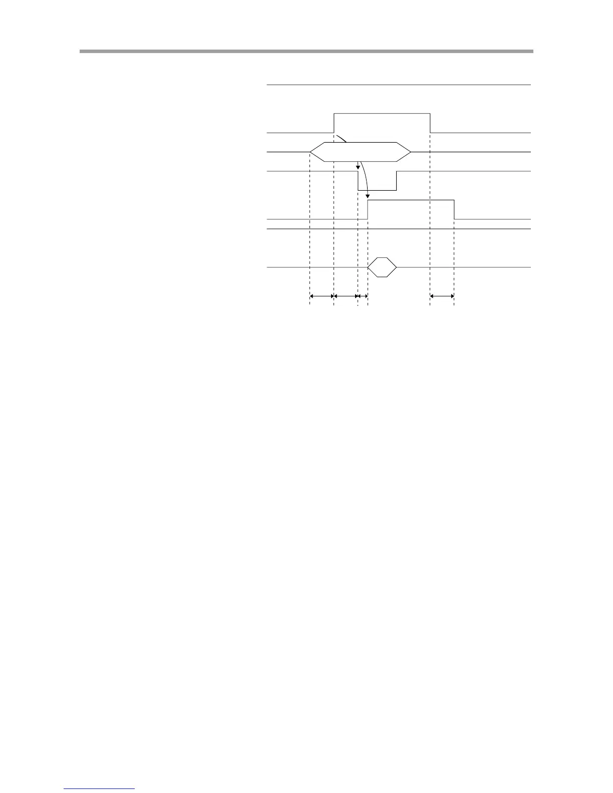
■ Point data write (PSET)
CHG
(
Mode switch input)
PSET
(
Point data write command)
(Point number designation inputs
200 to 205)
END
BUSY
READY
Point data write
Data retention
Point data writing
30ms or more 30ms or less 30ms or less1ms or less
PI200
to
205 *
*
The number of point number outputs that can be used depends on the I/O assi
nment type.
Precondition: The CHG signal is on before and during point data writing (until the
following procedure is complete).
(1) Designate the point number input (PI200 to PI205) to write the point data.
• The point numbers that can be used depend on the I/O assignment type.
Refer to the I/O assignment list in “2-9-2 Changing the I/O assignment”.
•The input status for designating the point number must be kept unchanged
until step (3) is complete. If this input status is changed, the controller
might misrecognize the data.
(2) After 30ms or more has elapsed, turn on the PSET.
(3) The END signal turns off and the BUSY signal turns on, indicating that the
controller received the point data write command.
(4) Turn off the PSET.
(5) Wait until the BUSY signal turns off.
(6) The BUSY signal immediately turns off since point data writing is already
finished. The END signal should be on at this point, indicating that the point
data writing was completed normally.