2.
Remove the valves. Mark each valve
so
it
will
be
reinstalled
in
the same cylinder
head.
NOTE:
______
__
____
______
____
__
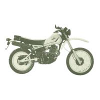
Deburr any deformed valve stem end.
Use
an
oil stone to
smoC'th
the stem end. This will
help prevent damage
to
the valve guide dur-
ing
valve removal.
~
-----+---?
DEBURR
----,f----
VALVE STEM
3.
Using a rounded scraper, remove the
carbon deposits from the combustion
chamber. Take care
to
avoid damaging
the spark
plug threads and valve seats.
Do
not
use
a sharp instrument. Avoid
scratching the
aluminum.
4. Check the cylinder head warpage with a
straightedge
as
shown.
The warpage
should
not
exceed the
specified
limit;
if
necessary, resurface
the
cylinder head. If the warpage ex-
ceeds
allowable limit, the cylinder head
should
be
replaced
with
a
new
one.
Cylinder head warpage:
less than 0.03 mm (0.0012 in)
Allowable limit: 0.25 mm
(0
.
010
in)
3-13
C.
Valves,
Valve
Guides,
Valve
Seats,
and
Valve
Springs
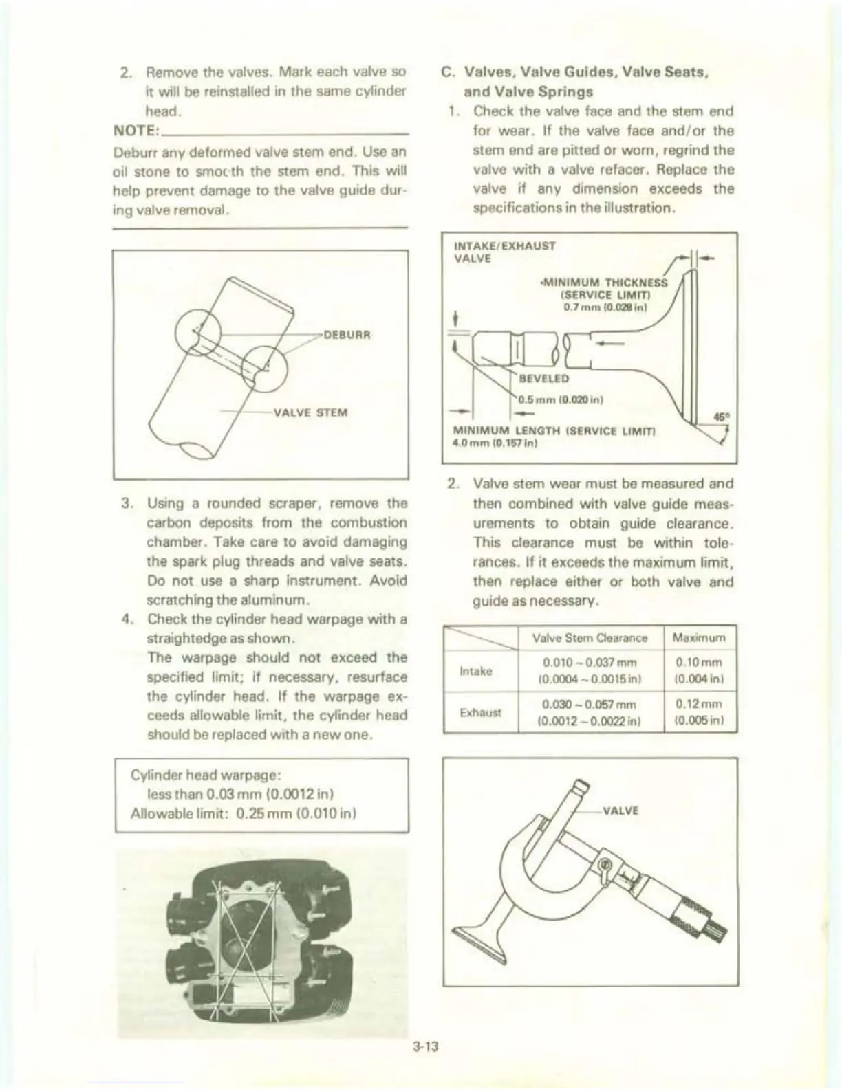
1. Check the valve face and the stem end
for wear.
If
the valve face and/ or the
stem end are pitted
Or
worn, regrind the
valve with a valve refacer. Replace the
valve
if
any dimension exceeds the
specifications
in
the illustration.
INTAKE/EXHAUST
VALVE
;:11-
t
--
·MINIMUM
THICKNESS
(SERVICE LIMIT)
0.7
mm
(0.028 in)
-
0.5
mm
(0.020
in)
--
MINIMUM
LENGTH (SERVICE LIMIT)
4.0
mm
(0.157
in)
2.
Valve stem wear must
be
measured and
then combined with
valve guide meas-
urements
to
obtain guide clearance.
This clearance must
be
within tole-
rances.
If
it exceeds the maximum limit,
then replace either or both valve and
guide
as
necessary.
----------
Valve Stem Clearance Maximum
Intake
0.010 - 0.037 mm
0.10mm
(0.0004 - 0.0015 in)
(0.004 in)
0.030
- 0.
057
mm
0.12mm
Exhaust
(0.0012 - 0.0022 in)
(0.005 in)