Crankshaft
1. Check crankshaft components per chart.
Check connecting rod axial play at
Small end play should not exceed 2
If small end play exceeds 2 mm
small end (to determine the amount
mm (0.079in).
(0.079 in)
disassemble crankshaft,
of
wear
of
crank
pin
and bearing at
check connecting
rod, crank pin
big end).
and big end bearing.
Replace defective parts.
Play
after
reassembly should
be
within 0.8 -
1.0 mm
(0.031
- 0.039 in).
Check the
connecting rod side Move the connecting rod to one
If excessive axial play
is
present,
clearance at big end.
side and insert a
feeler gauge.
Big
0.7 mm (0.028
in)
or
more,
end axial play should
be
within 0.35
disassemble
the crankshaft and
-
0.65 mm (0.014 - 0.026 in).
replace any worn parts.
Check crankshaft assembly runout.
Dial
gauge readings should
be
Correct any misalignment by tapp-
(Misalignment
of
crankshaft parts.) within 0.03 mm (0.00118 in).
ing the
flywheel with a
brass
ham-
mer and by using a wedge.
Crankshaft Specifications
Unit: mm (in)
Rod
clearance
Runout
limit
Assembly
width
C A
Min.
0.03
74.95 - 75.00
0.8
(0.0012)
(2.951 - 2.953)
(0.03)
F
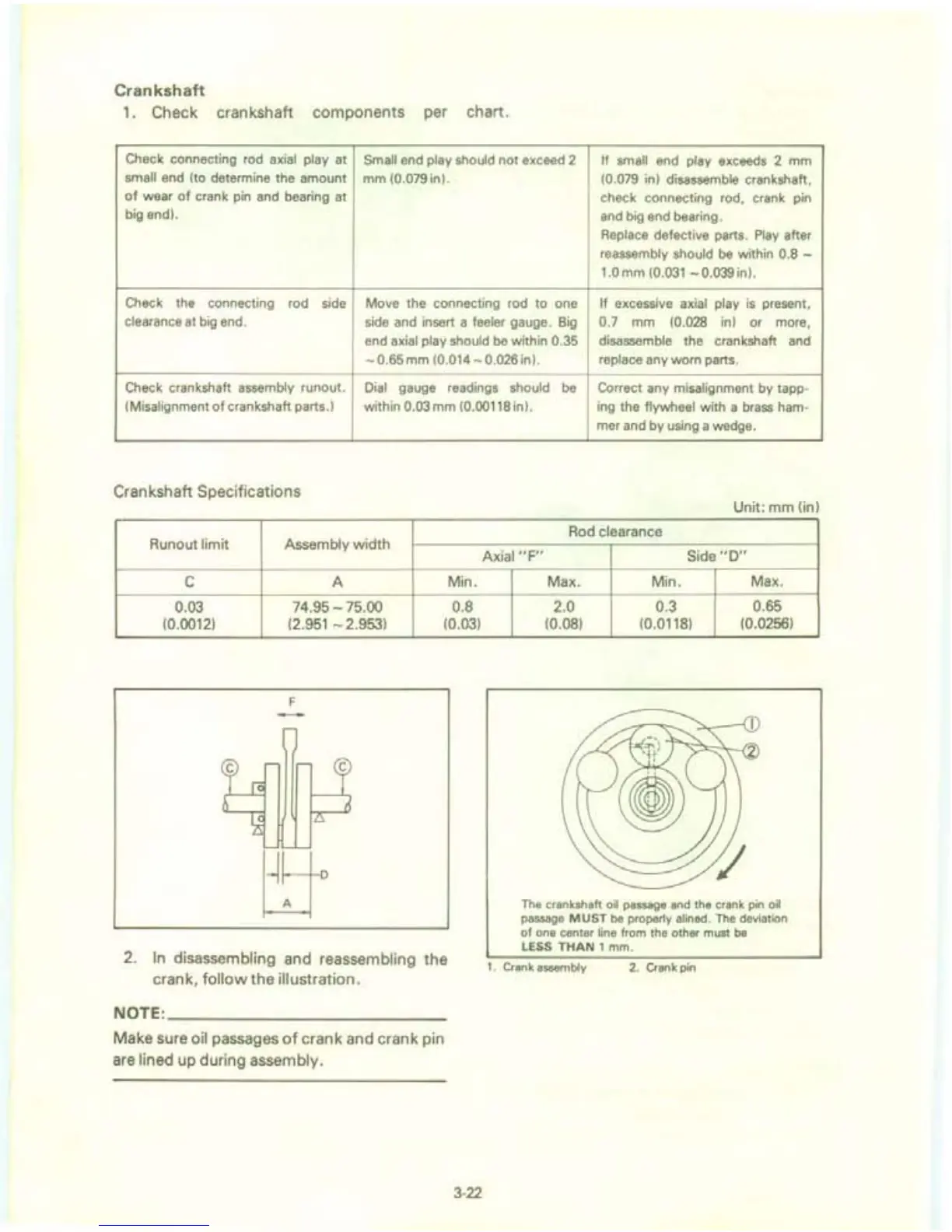
2.
In
disassembling and reassembling the
crank, follow the illustration.
NOTE:
___________
_
Make sure oil passages
of
crank and crank pin
are
lined up during assembly.
3-22
Axial
"F"
Side
"0"
Max.
Min.
Max.
2.0
0.3 0.65
(0.08)
(0.0118) (0.0256)
The crankshaft oil passage
and
the crank pin oil
passage
MUST
be
properly alined. The deviation
of
one center line from the other must
be
LESS
THAN
1 mm.
1.
Cran
k assembly
2. Crank pin