ENGINE
Camshaft and Timing Gear Train
5-46 BY Service Manual
© 2009 Yanmar Marine International
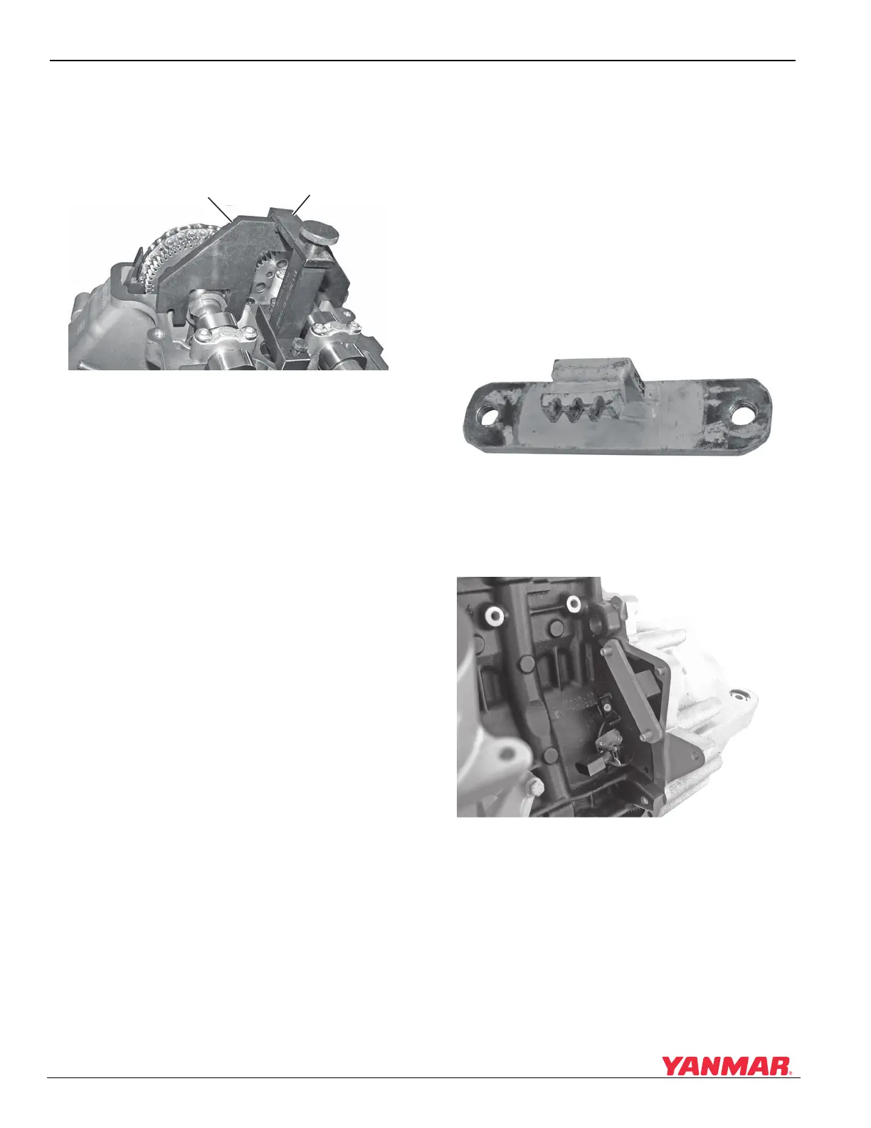
7. Install special tool OEM No. 11 6 321
(Figure 5-80, (1)) on the flats of the intake
camshaft and secure with special tool OEM No.
11 6 322 (Figure 5-80, (2)). Secure to cylinder
head with two bolts.
Figure 5-80
Figure 5-80
Note: Special tool shown on intake camshaft.
Exhaust camshaft is checked in the
same manner but has no adjustment. If
camshaft gears are properly aligned,
exhaust camshaft timing will be correct.
8. Tighten the two exposed sprocket retaining
bolts to 15 N·m (133 in.-lb).
9. Remove special tools.
10. Rotate the crankshaft 360° to expose the
remaining sprocket retaining bolt and tighten to
15 N·m (133 in.-lb).
11. Install cylinder head cover. See Remove and
Install Cylinder Head Cover on page 5-17.
Remove and Install Vibration
Damper - 4BY2
1. Disconnect battery negative (-) cable.
2. Remove alternator and seawater pump drive
belts. See Remove and Install Alternator on
page 11-5 and Replace Seawater Pump Belt on
page 7-19.
3. Remove starter motor. See Remove and Install
Starter Motor on page 10-5.
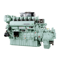
Note: A shop-made flywheel holder can be
fabricated using a piece of a used ring
gear (Figure 5-81).
Figure 5-81
Figure 5-81
4. Install flywheel holder to prevent crankshaft
from rotating (Figure 5-82). Mount the tool
using the starter mounting bolts.
Figure 5-82
Figure 5-82
5. Remove the vibration damper bolt.
6. Remove flywheel holder and remove damper.
7. Place vibration damper on crankshaft and
install new bolt and washer until vibration
damper is snug.
0003773
(1)
(2)
1
0003832