COOLING SYSTEM
Cooling Flow Diagram
7-6 BY Service Manual
© 2009 Yanmar Marine International
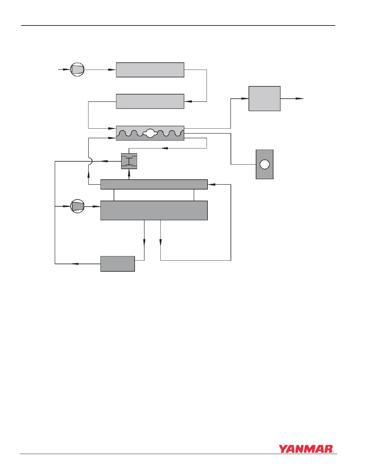
COOLING FLOW DIAGRAM
Figure 7-1
Figure 7-1
Note: Typical 4BY2 engine shown. 6BY2 is similar.
1 – Seawater Supply
2 – Seawater Pump
3 – Hydraulic Oil Cooler
4 – Charge Air Cooler
5 – Engine Heat Exchanger
6 – Exhaust Seawater Mixing Elbow
7 – Exhaust / Seawater Exit
8 – Engine Coolant Pump
9 – Thermostat
10 – Engine Oil Cooler
11 – Engine Coolant Passages
12 – Coolant Recovery Tank
13 – Water Cooled Exhaust Manifold
(2)
(1)
(3)
(4)
(5)
(6)
(7)
(12)
(13)
(9)
(8)
(10)
(11)
0006511