ELECTRICAL AND ECU
Function Description - Engine Management System
12-8 BY Service Manual
© 2009 Yanmar Marine International
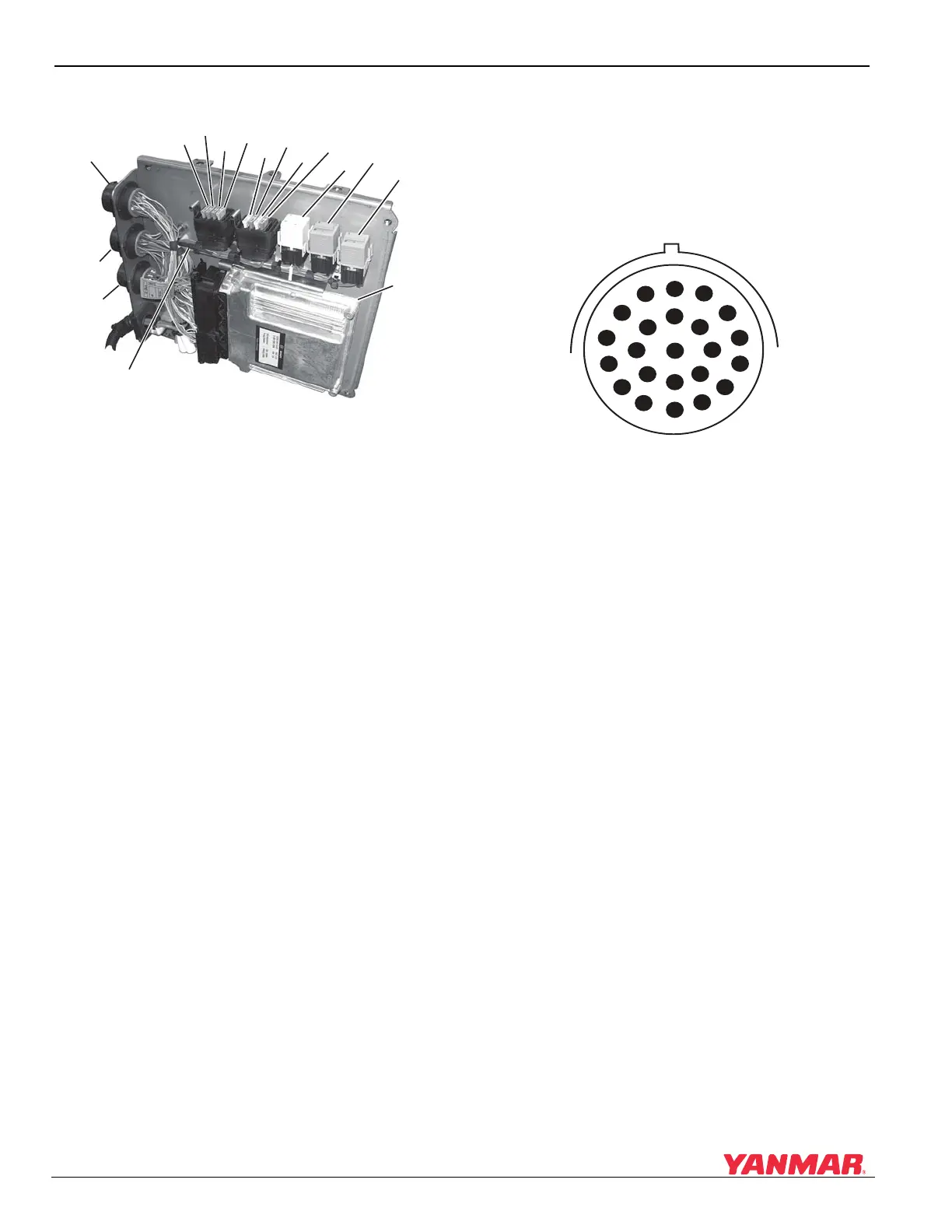
Electrical Panel Components
Figure 12-3
Figure 12-3
1 – Fuse F1 (3 A) - Switched B+ to CAN
2 – Fuse F2 (10 A) - B+ to Key Switch
3 – Fuse F3 (15 A) - Fuel Supply Pump
4 – Fuse F4 (30 A) - Switched B+ to ECU
5 – Fuse F5 (20 A) - Power to Sensors and
Actuators
6 – Fuse F6 (10 A) - Auxiliary Power
7 – Jumper Fuse F7 (3 A) - Single / Port
Selection, default is single / port (fuse in).
Remove fuse for starboard configuration.
8 – Jumper Fuse F8 (3 A) - CAN / Analog
Throttle Selection, default is analog (fuse
out). Insert 3 A fuse to configure for CAN.
9–K1 - Starter Relay
10 – K3 - Fuel Supply Pump Relay
11 – K2 - Main Power Relay
12–ECU
13 – Connector X1 - Communication to Helm
Display
14 – Connector X21/1 - Engine Wiring Harness
15 – Connector X22/1 - Fuel Injector Wiring
Harness
16 – Blocking Diode V1
NOTICE: The electrical panel cables must be
connected directly to the battery, and must have a
circuit breaker installed in the B+ (red) lead.
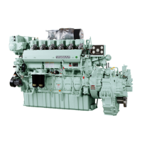
Electrical Panel Connector (X1)
Connections
The ECU is connected to other components and
systems via connector X1 (Figure 12-4). The
graphic and table show the pin locations and
assignments.
Figure 12-4
Figure 12-4
0003372
(
1
)
(
2
)
(
3
)
(
4
)
(
5
)
(
6
)
(
9
)
(
10
)
(
11
)
(
12
)
13
)
(
14
)
(
15
)
(
16
)
(
7
)
(
8
)
W
X
K
V
J
B
L
U
H
T
G
A
C
M
N
D
E
F
S
R
Q
P
O
0003304